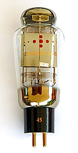
EML45 Data Sheet
Guarantee program for first owner.
At EML we have the normal guarantee. In addition to that, the first owner can register the tube within 4 weeks after receival, at the Emission Labs website, to participate in the 5 years guarantee program.
Register here for the 5years guarantee
Gold Grid
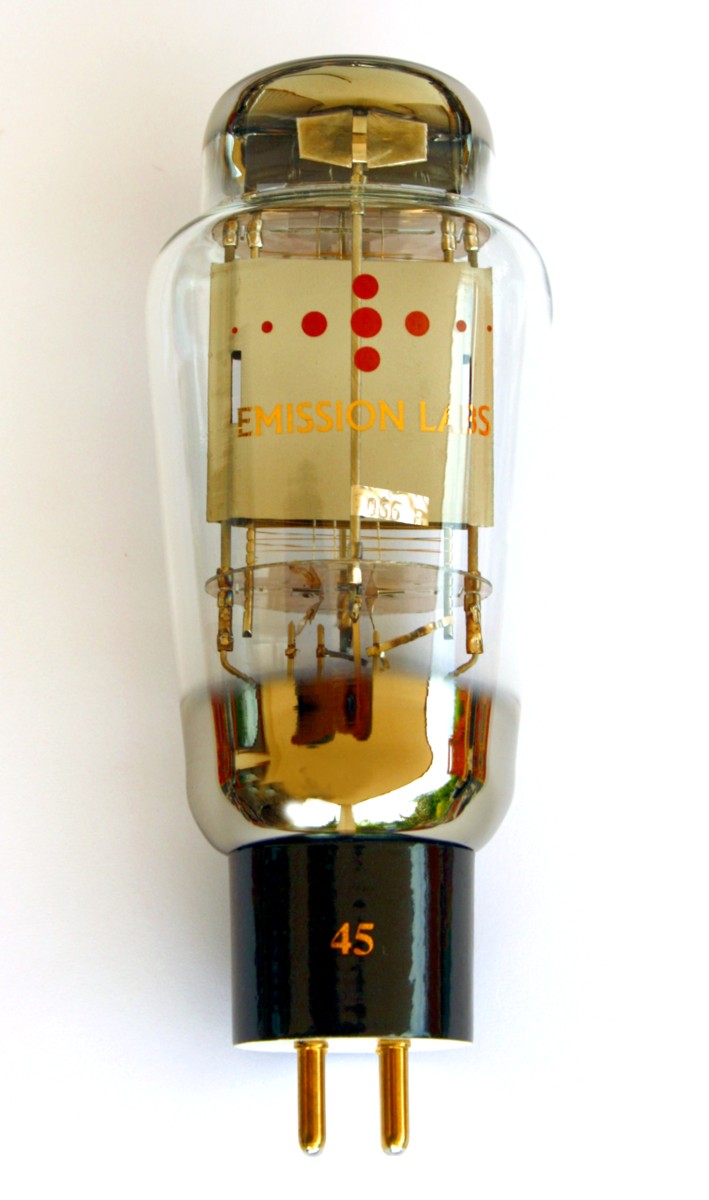
We have added a gold grid to all EML tubes, some time ago, also to the 45. Very few NOS tubes have this. You can see the gold color of the grid wire when you look into the tube in the sunlight. The gold grid will give better bias stability, and you will may see the EML tubes bias perfectly right out of the box, and no bias change during burn in. Also read the next table 'features'. As an overall total result, the standard 45 is a no compromise replacement for the original RCA 45. Check also the 45-mesh data sheet.
Features
- Nano Ampere range grid current, vs NOS tubes which can have sometimes 2uA.
- Cathode Tapped filament
- 30% lower distortion compared to any other 45. Read here.
- Hard metal Construction (Note1)
- Extra large getters
- Hand blown Glass bulb
- Anti-microphonic Anode- and grid suspension
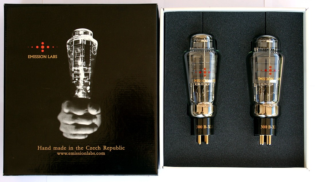
- These tubes are shipped in a high quality dual box
- Tube printing with real gold (metal), red color is glass burned into the glass
- YAMAMOTO tube sockets highly recommended.
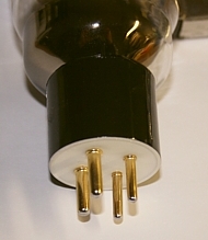
- Gold Plated pins, black ceramic socket. (White bottom.)
Sound Character of the EML 45
We are often asked to describe the sound of our 45 tubes. If you are looking for real triode sound, the 45 tube is very interesting. It is important that tubes and speakers fit together well. So low power tubes sound best at high efficiency speakers, and vice versa. Best sound of the 45 is developed at the very sweet first Watt. The 45 will reward you with best sound when you are using high efficiency speaker systems, starting at 96..99dB. At the same time, here comes a drawback for the amplifier and the tubes as well. Such speaker systems of 100dB and above will make smallest imperfections audible, and the amplifier must produce as little hum and noise as can be. This is difficult. When you are thinking of 108db horn systems this stresses the design limits of tubes and amplifiers a lot. A quick way to test the noise level of your amplifier-tube combination is, to measure the AC signal out of the amplifier with the inputs muted, but the speaker connected. Anything below 3 millivolt at 8 Ohms is a good achievement, and such an amplifier below 1 millivolt can be called a fine piece of work. If an amplifier will produce low hum with many different tubes, this is definitely a better design, than such an amplifier that is critical on the tubes. Of course, here the tubes play a major role too. At EML we have greatly reduced hum and distortion of all tubes, by a new filament construction. This was done by a real, physical filament Cathode Tap, that is positioned outside of the Anodes, but inside the glass bulb. The result was, we reduced the hum level of the EML45 even below that of many good NOS tubes.
![]() We have two versions for the heater: Normal heater, or Cathode Tapped heater. Here is a link to Application Note 06, describing the Cathode Tapped tubes in general. Link here.
We have two versions for the heater: Normal heater, or Cathode Tapped heater. Here is a link to Application Note 06, describing the Cathode Tapped tubes in general. Link here.
Distortion of the EML45, versus Power Output
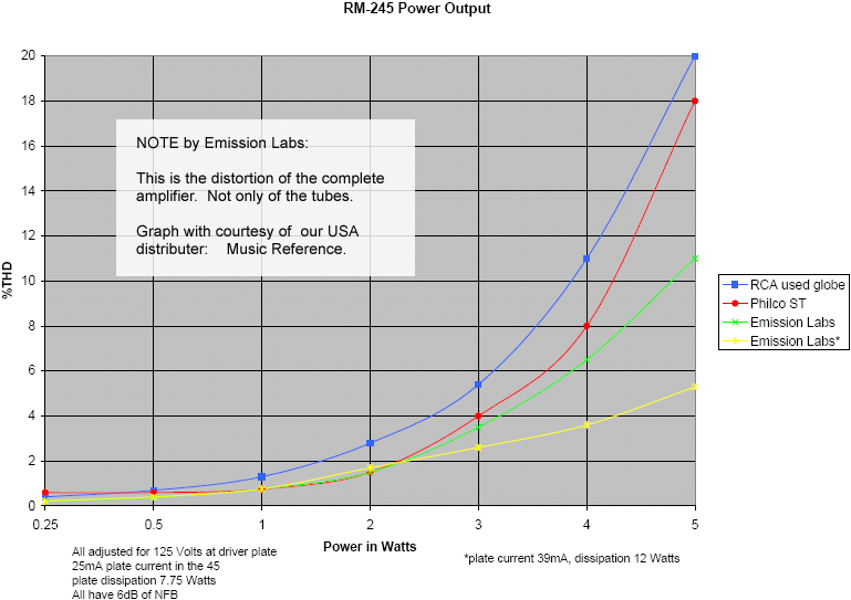
Distortion of the EML tubes is probably the lowest you can have. Here is a link to detailed test results, made for us by Roger Modjeski from RAM LABs, USA. From this you can see, the EML 45 is having the best results, most specially at higher signal level. For equal loudness, the human ear needs higher power at lower frequencies, and this is present in all music in a natural way. The result is though, bass tones of amplifiers have the highest electrical signal level, so bass distortion appears always first. This will change the sound character, making the bass less 'dry'. At medium volume you don't hear this as distortion. What you do hear is, the overall sound picture gets less precise, less natural, and it makes your ears tired from listening sooner. This is a very important mechanism to understand. The EML45 tubes give a strong contribution here, by reproducing the bass sound with smallest distortion a 45 tube can do.
EML 45 Filament Ratings |
|
| Filament Voltage | 2.5Volt (AC or DC) |
| Electronic heater modules: | Only voltage source |
| Tolerance on filament voltage | 5% |
| Filament Current | ~ 1.5Ampere |
| Maximum Time on Stand By (Heater voltage only) | 2 hours |
EML 45 Maximum Conditions |
|
| Anode Voltage | 300Volt |
| Anode Current | 45mA |
| Continuous Anode Dissipation | 11Watt |
| Power Output in Class A | 2.5 Watt |
| Grid resistor, highest possible value (Important: Note5) |
500k Ohm |
EML 45 Factory Test conditions |
|
| Anode Voltage to Cathode | 250V |
| Anode Current | 34mA |
| Grid Voltage | at above conditions |
| Transconductance | at above conditions |
EML 45 Typical Data |
Single Ended |
|
| Anode Voltage to Cathode | 250V |
275V |
| Anode Voltage to Ground |
300V
|
331V |
| Anode Current |
34mA |
36mA |
| Anode Dissipation | 6.8Watt |
7.9 Watt |
| Cathode resistor | 1470 Ohm |
1550 Ohm |
| Cathode Resistor voltage | 50Volt |
56Volt |
| Anode Impedance (Rp) | 1750 Ohm |
1670 Ohm |
| Load Resistance (Ra) | 3900 Ohm |
4600 Ohm |
| Amplification Factor | 3.5 |
3.5 |
| Transconductance (Gm) | 2mA/V |
2.1mA/V |
| Power Output in Class A | 1.6 Watt |
2 Watt |
| Total Distortion | 5% |
5% |
EML 45 Typical Data (2) |
PUSH PULL |
|
| Anode Voltage to Cathode | 250V |
275V |
| Anode Current 2) 3) | 68mA |
72mA |
| Anode Dissipation 1) 3) | 6.8Watt |
7.9 Watt |
| Cathode Resistor 2) | 735 Ohms |
775 Ohms |
| Bias voltage | 50Volt |
56Volt |
| Load Resistance (Ra) | 4200 Ohm |
3900 Ohm |
| Power Output in Class A 2) | 4.6Watt |
5.5 Watt |
| Total Distortion | -40dB |
-40dB |
1) Values for one tube |
||
EML 45 Typical Data (3) |
PUSH PULL |
|
| Anode Voltage to Cathode | 275V |
300V |
| Anode Current 2) 3) | 67mA |
64.5mA |
| Anode Dissipation 1) 3) | 7.3Watt |
7.6Watt |
| Anode Dissipation 1) 4) | 8.4Watt |
8.2Watt |
| Cathode Resistor 2) | 850 Ohms |
1000 Ohms |
| Bias voltage 3) | 57Volt |
64.5Volt |
| Bias voltage 4) | 69,7Volt |
72Volt |
| Load Resistance (Ra) | 4000 Ohm |
5000 Ohm |
| Power Output in Class A 2) | 6Watt |
7.4 Watt |
| Total Distortion | -34dB |
-40dB |
1) Values for one tube |
||
EML 45 Typical Data (4) |
PUSH PULL |
|
| Anode Voltage to Cathode | 275V |
275V |
| Anode Current. 2) 3) | 72mA |
72mA |
| Anode Current. 2) 4) | 90mA |
97.4mA |
| Anode Dissipation. 1) 3) | 7.9Watt |
7.9Watt |
| Anode Dissipation. 1) 4) | 9.2Watt |
9.7Watt |
Input Signal, RMS. 1) 4) |
37.5V |
39.2V |
| Input Signal current. 1) 4) | 7.5mA |
5.3mA |
| Cathode Resistor. 2) | 775 Ohms |
775 Ohms |
| Bias Resistor voltage. 3) | 56Volt |
56Volt |
| Bias Resistor voltage. 4) | 69.5V |
75.5V |
| Load Resistance (Ra) | 5810 Ohm |
5420 Ohm |
| Power Output in Class A 2) | 12.7 Watt |
13.2 Watt |
| Total Distortion 5) | -26dB |
-26dB |
1) Values for one tube |
||
Recommended Singe Ended transformers |
|||
Primary |
Output |
Remark |
|
| LL1663-040 Lundahl |
5000Ω |
8Ω |
Budget transformer. No housing, and only one output impedance. |
| LL1682-050 Lundahl |
5000Ω |
5Ω |
Budget transformer. No housing, and only one output impedance. |
| LL2752-060 Lundahl |
4600Ω |
Alt.C =8Ω Alt.D =16Ω |
This transformer can be rewired for 8 or 16 Ohms (no taps). The primary is ideal for 275V use. |
EML 45 Mechanical Data |
||
 |
 |
Size including Socket 145 x 58 mm Weight of one tube: Shipment weight for Pin 1: Heater1 |
Ceramic UX4 Base |
||
 |
 |
Size including Socket Weight per tube: 140 Gram Pin 1+2: Heater1 |
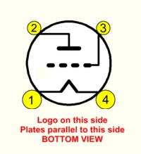
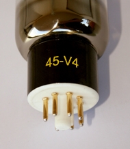
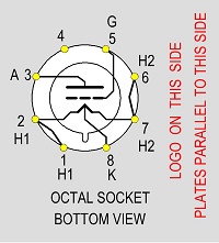
Ceramic Octal Base, V4 Version |
||
Note 1) Hard-metal filaments prevent filament breakage with DHT Tubes. This material has a higher melting point than classic nickel wires. Wolfram grids allow the most precise grid wire distance, because wolfram is an extreme hard metal. This ensures better grid precision, which gives uniformity and better linearity at the low end of the tube curves
Note 2) Individual Test data: Control Grid Voltage, Anode current, Transconductance and Filament Current is the test certificate that is on the outside of the box. Each tube is numbered, inside the bulb with a metal Tag
Note 3) Tube Curves: Made on the The Sofia Curve tracer, with courtesy of AMR, Wisconsin, USA.
Note 4) The V shaped filaments will give different electrical fields inside the tube, as compared to parallel filaments. For keeping the original character of this tube, we choose for V-shaped filaments.
Note 5) EML45 first generation (from before 2004) have a maximum grid resistor value of 100k. For tubes after 2004 we have this specification: Auto Bias: 500k. Adjustable bias 100k. As a rule of thumb, the coupling capacitor value is calculated as: C[μF]=47/R[kΩ]. So in this formula, the value of R is in kΩ, and the result is then in μF. Example: A grid resistor of 470k would need a coupling capacitor of 47/470=1μF.
Note 6) In a class AB2 amplifier, the tubes are operated mildly into positive Control Grid Voltage, and output power as published here should not tried to be exceeded. The 2nd Harmonics resulting from this, are cancelled by virtue of the Push Pull circuit. A sufficient low impedance driver stage is needed for class AB2. This can be achieved with a step down inter stage transformer, as recommended by the RCA receiving tube manual 1934, Page 93.
Note 7) A quick way to test the hum level of a amplifier, is to measure the AC signal the speaker terminals, with the inputs muted, but the speaker connected. Anything below 3 millivolt at 8 Ohms is a good achievement, and such an amplifier below 1 millivolt can be called a fine piece of work. If an amplifier will produce low hum with many different tubes, this is definitely a better design, than such an amplifier that is critical on the tubes.