AN-06. Center Tapped Heater, for directly heated tubes
Abstract
With directly heated tubes, the filament is the cathode at the same time. In some way, we need to use the filament as a cathode, but the filament has two electrical connections. How to connect this, has been an engineering issue ever since. Good and clever solutions, we see as well, as mistakes and plain stupidities, also with professional companies. Even so, it seems often to me, DIY pay a lot more attention to tube reliability and safe design.
There is no ideal way to connect a directly heated tube cathode, but we must not see of this as a problem, because their distortion is much lower than directly heated tubes anyway. Reason for this is the circular structure of indirectly heated tubes, versus the planar structure of indirectly heated tubes. Electrical fields in a planar structure will stretch out linear. Whereas electrical fields in a circular structure have to expand on their way to the anode, causing signal distortion one way or another.
How to connect a directly heated tube filament the best way.
There is probably agreement, that the best way to connect, is they way giving the least distortion. We come to this right away. There is however also the safety issue:
A word about safety.
I really would like to add to this also, it is no good to use self designed electronic regulators with a series transistor. Unfortunately, the failure mode of an over heated transistor is always a short, and the result of that is a burned out tube heater. Before you can say, yes I use a particular transistor, you should look up in the data sheet, it's MTBF (Mean Time Between Failures) and use the manufacturers formulas or charts, to derate this number to the temperature you are using it at, and calculate the expected (!) failure rate from this. For you, this means not only a failed transistor, but also a failed tube. This is why a good brand, ready to use Integrated Circuit works so much safer. The difference in reliability of a self designed PCB, versus an Integrated Circuit, is large. Very, very large. A good IC has current limiting, they are short proof, have soft start, temperature protection, etc. When using a 2A Version for a 1.5A tube, you have the best soft start you can think of. These start up in current limited mode at 2A, and then go to 5V mode, when current drops to 1.5A. All of that for a price of less than 1 Euro.
The highest safety you get from a switched mode power supply, since these do not short the input to the output in case of a failure. These have a price of less than 20 Euro, and do not even need a mains transformer.
The best and fastest way to connect the V4-tubes. (Center tapped tubes)
Connect a floating power supply to the heater connections, called H1 and H2 in the datasheet. Now, the question is, where is the cathode? As a cathode, use the Center Tap. So connect the auto bias resistor, to the Cathode Tap, and regard it the cathode. Already the tube will work, with less parts, and better technical result than any other method.
Old School schematics (symmetric connected)
In most tube schematics we see two centering resistors at the filament. The point were these two are connected, becomes an artificial cathode. Even so when the two resistors are identical, there is still a small offset, because tube geometry is never ideal. To overcome this, a potentiometer can be added, to center the artificial heater, adapted to the individual tube.
New School schematics (unsymmetric connected)
This seems to be, to ground the heater with one end, and connect a DC voltage to the other. This disadvantage of this is, you can not have auto bias any more, and power tubes can not be used up to their full capabilities without auto bias. Besides this connection scheme is a lot more suspectable to hum, because the tube heater is connected unsymmetrical. Any hum on the heater, will be amplified by the tube gain. Whereas with symmetric connection (see above) the AC rejection is so high, you could even use just an AC voltage to heat the tube.
Yet this way to connect had gained some popularity, because it is easy to do. Also because there is such incredible nonsense told about driving heaters with a current source, to reduce distortion. I have read these so called technical background articles about it. There are many mistakes in there, only trying to sell modules. You should better use an 7805 integrated circuit. it works a lot safer. Really, if you want to reduce distortion, and heat the tube symmetric, also called balanced. (Schematic #2 below here).
Is there a better solution?
Yes there is! It is called the Center Tapped tubes by Emission Labs.
How and why this works so much better, is hard to explain in just a few words. Please take some time to compare these three schematics below here, try to understand their advantages and disadvantages.
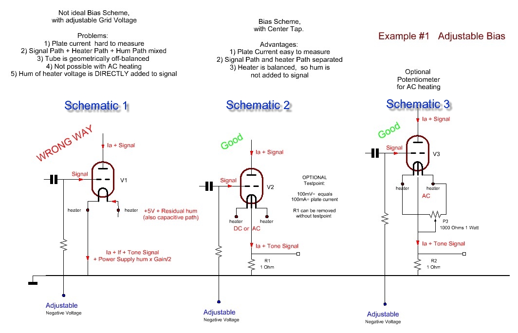
Above: Classical filament vs Center Tapped filament - Adjustable Bias
From the above left schematic #1, it can be seen there a common path for the Music signal, and the heater current. Needless to say this is source of problems.
The middle schematic has so much simplicity, it may seem familiar to you. Though this is a new method. The advantages are:
- Anode Current is easy to measure (This is impossible with the left schematic)
2) Signal Path and heater Path separated. - Heater is balanced, so hum is not added to signal.
- The schematic on the right, shows how to add a hum potentiometer, in case you heat with AC and you don't want to do without a hum potentiometer.
BLACK BOX APPROACH
It is widely unknown, that Directly Heated Tubes (DHT) have a very high rejection ratio of the AC heater signal. For this reason, the left schematic (above) is a bad one to use. Let's just look at a tube as a black box, which is an amplifier in our case. So, something goes in, something goes out, and we have gain. There are two power supplies connected, with some amount of AC hum on it. This hum we want rejected.
 Above: Black Box model of a tube.
We consider the rejection ratio for the schematic 1, but to make it simple we just use a numerical example. Suppose the input, IN1 = 1V~, and the tube gain is 4. Then we have 4V~ on the output, called 'Out'. So far, so good, and we all know that. There are three signals, applied to the tube, but power supply ripple we are not looking at here. So we consider only the AC heater 'Signal' and the Tone input signal. Of course we expect nothing of the AC heater signal to appear at the output. However, since our black box is not ideal, something will appear at the output still.
Considerations for the above schematic #1
There is no rejection of the heater AC residue. In fact it is even amplified by the tube, when it's gain is higher than 2x. So the output signal will be:
Out = IN1 * Gain + IN2 * Gain/2. In a practical situation, a 300B amplifier can be considered low hum, when you have less than 1mV AC on the 8 Ohms speaker output, whereas not so good amplifiers present 5mV hum or more. We calculate here with the 1mV. This translates into appr 20mV on the tube anode. We are going to assume now, all of that is injected via the heater. How much would it need on the heater, to get 1mV on the speaker (meaning 20mV on the Anode). 20mV on the anode, with a gain of four, means 5mV on the grid. Or, we can have 10mV on the heater, which has the same effect.
So, 10mV AC on the heater gives 4 x 5mV AC on the anode, so 20mV . This is a GAIN of factor 2 (or 3dB)
Conclusion for Schematic #1: For each 10V on the heater, you get 1mV on the speaker. Rejection -3db / Gain of 3dB (!) |
Considerations for the above schematic #2
This one works much better. It can be compared with a classical AC heated schematic, and without a Center Tapped potentiometer, you can come down to say 8mV on the speaker output. This is for full 5V AC signal, on the heater, or input 'IN2'. This 8mV on the speaker would mean 32mV on the Anode. This is a REJECTION with factor 156 (or 22dB). We can reduce the 8mV on the speaker to 1mV, which would reduce the 5V AC voltage to 625mV
Conclusion for Schematic #1: For each 625mV on the heater, you get 1mV on the speaker Rejection 22dB |
How to design?
Whatever you do, schematic #1 has no preference, since it has no ripple rejection, but 3dB ripple GAIN (!!!). Such a schematic will only work with extremely quiet DC power supply, and yet not make ideal use of the tube still. It is much better to use schematic #2, since it's ripple rejection ratio is so high, you can do without electronic regulation. Simply a passive stabilized circuit will do the job. Like a plain C-R-C circuit is FINE already, and will outperform circuit #1 using an integrated circuit. So the difference between schematic 1 and 2 is 25dB less heater hum.
So where does the Cathode Tap come in?
You may object, schematic #2 can be achieved also with two centering resistors. This is true, but not quite. If you want really good centering, you will need very low values of those resistors, and they use considerably energy. This makes the power supply capacitors larger, the transformer also, and you have larger charge peaks for the capacitors, which will radiate into other parts of the amplifier. So the resistors are chosen often at a much higher value, to make things more practical. Then, in the end they become a bad compromise, and you loose the good rejection ratio you had in mind. Note, when they get too high, you also start to dump output signal in those resistors, as the anode signal must pass through them. So the amplifier gets less efficient. In a practical situation we talk about 0.3 Watt loss in a 300B Single Ended stage. Also the artificial center is connected via a resistive path, and all of this is not a clean and nice way.
The Center Tapped tubes do a much better job here. They are not a compromise, they give a real true Cathode Tap, directly on the cathode itself, and yet it consumes no heater power.
The advantage with high gain tubes:
As the heater ripple gets amplified by half the gain of the tube, the V4 version becomes very useful with tubes, such as the 20A, 20B, or 30A.
The advantage with high power tubes:
Since you loose appr 3% of the tube output power in those centering resistors, it is simply nice to have 3% more output power from a Center Tapped tube.
The advantage with low power tubes:
Such a tube is often used with very high efficiency speakers, and anyone who has experience with such speaker systems will know that residual hum is a major issue. It is obvious that 2mV hum from the amplifier. is very unpleasant with 106dB speakers, but you won't hear it with 90dB speakers. So with horn systems, when using the V4 tubes, you are likely to get lower hum, since you are better protected from some of the very nasty, and unexpected mechanisms that cause your amplifier to hum via the power supply.
Can you use them as normal tubes?
Yes you can! If you don't want to use the Cathode Tap, just leave it disconnected and you have a regular four-connection DHT triode again.
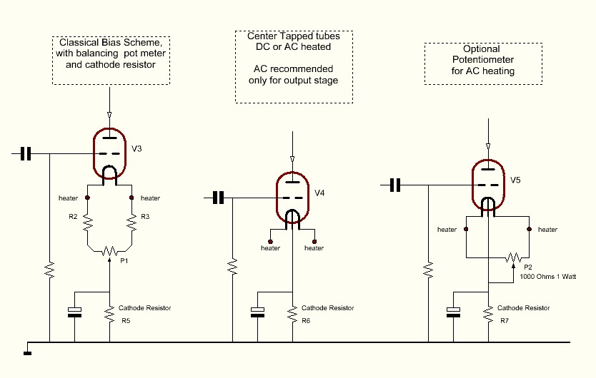
Above: Classical filament vs Center Tapped filament - Auto bias
You are encouraged to discuss it on the EML forum!
For amplifier designers, the below links may be helpful.
1. Warning by OSRAM, about design issues, which causes sparking tubes:
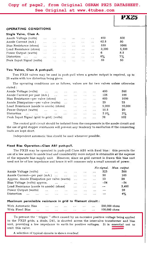
2. Table of lowest allowed transformer windings resistance:
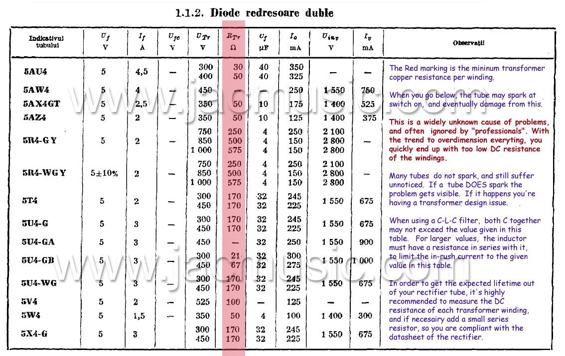
3. Warning by RCA, about design issues, which causes sparking tubes:
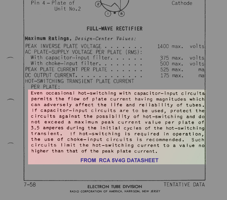
4. Our Application Note for amplifier manufacturers: