EML80A Data Sheet
Description
 |
This tube has the designation "80A", indicating it is a special version of the "80" tube. The difference is two:
More about this, in the description below here. |
Description
The 80 rectifier was a standard rectifier in American Radios. These radios worked typically at 250V DC. To avoid the use of a power supply choke, they used relatively high first capacitors. Due to this low voltage, the "Type 80" was relatively low cost, and it became very popular.
The 274A rectifier has also a 2 Ampere heater and UX4 socket. It was however intended for higher voltage applications, which was achieved by a better tube socket, and more isolation distance with the mica parts and the tube stem. The drawback of the much higher voltage, is a smaller maximum value of the first capacitor.
The emissionlabs 80A can fulfill both requirements: The large capacitor of the 80 at low voltage, and the high voltahe of the 274A with a smaller capacitor.
With rectifier design in general, to achieve ultra low ripple, it is recommended to use the Lundahl LL1673 dual coil choke in what is called: "CMR" configuration. A large choke needs no high first capacitor, can take a higher second capacitor much better, and there will be virtually no hum field radiation from the choke itself. (See link to circuit diagram, at the bottom of this page).
Guarantee program for first owner.
The first owner can register the tube within 4 weeks after receival, at the Emission Labs website, to participate in the 5 years guarantee program, which is additional to the legal obligations of the seller.
Register here for the 5years guarantee
Features
- Hard metal filaments (See Note1), series connected.
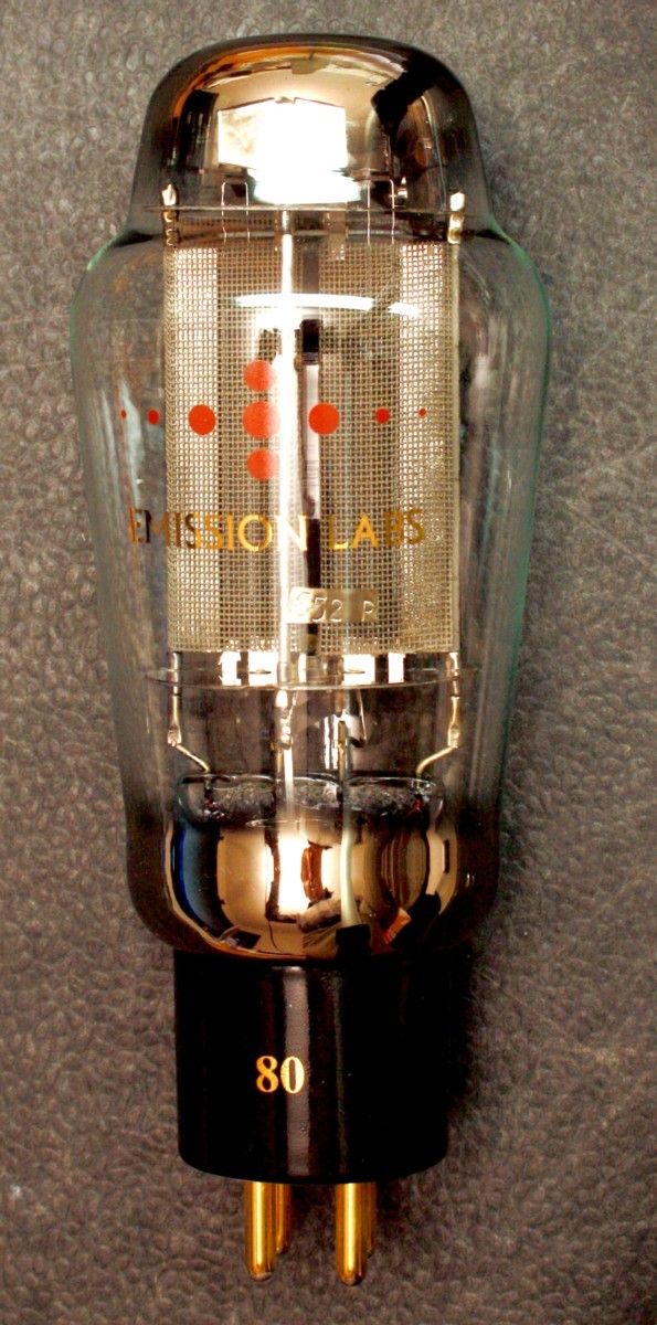
- Each tube is numbered, inside the bulb with a metal Tag
- Hand blown, Globe shaped glass
- Extra large getters.
- These tubes are shipped in a high quality dual box or single box for rectifiers.
- Tube printing with real gold (metal), red color is burned into the glass.
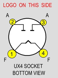
- Gold Plated pins, black ceramic UX4 socket. (White bottom). Ideal for the YAMAMOTO tube sockets.
Typical application notes below here, applies for 80 and the 274 tube.
Sound Character of the 80 Rectifier
It is the most asked question, and behavior of a power supply depends a lot on the type of tube rectifier used, and the way it is used.
The 80 rectifier was intended for small radios, where it cooperated with output tubes like the 45 Triode and 47 pentode. Radio receivers usually operate at 250V DC. This voltage was easy to achieve, and enough for amplifier tubes. However for a triode as output tube, 250V was a compromise in terms of output power. Otherwise the whole radio had to be designed for higher voltage, which was more expensive. Yet for higher power output, a higher working voltage of 275V was used, as found in more expensive radios and audio amplifiers. The 80 tube was designed for both applications, and still today the ideal choice for small HiFi amplifiers, or pre amplifiers. It can be regarded as a smaller version of the 5U4G, but the 80 has higher plate impedance, which is of advantage for low hum circuit design.
The maximum capacitor value for the 80 tube was limited at 20uF. The 80 rectifier is quite robust, because the relation of maximum capacitor value compared to the heater current is better than with 5U4G. For this reason, collectors often find the original 80 rectifier still working in old radios.
Overall it can be said, the 80A rectifier is a very reliable tube, and comfortable for the electronics designer, due to it's relatively high possible first capacitor. Other than 5U4G, this tube is characterized by higher dynamic resistance, thus reducing power supply hum, and radiation of hum into other parts of the circuit. Also for head phone amplifiers, it makes this tube a very good choice.
Filament Ratings |
|
| Filament Voltage | |
| Tolerance on filament voltage | |
| Filament Current | |
Maximum ratings if transformer 350V AC
|
||
AC in |
DC out |
|
| Capacitor Input | 350 |
125mA |
| Transformer Raa minimum value. (Add normal resistor, if your Raa too low) | 200 Ohms |
|
Maximum ratings if transformer 350V AC
Max limits NOT possible simultaneously |
|
| DC output current | 160mA |
| Choke Input | 550Volts |
| Capacitor Input | 450Volts |
| First capacitor, connected to Anodes | 4uF |
80A Mechanical Data |
|
|
Size including Socket 140 x 58 mm |
Tube weight: |
|
Shipped weight for a single boxed tube: |
|
Notes
- Good care should be taken when making the design of any DHT rectifier. It must be prevented to have strong current peaks, through the first capacitor, because consequently this flows through the tube anode, and transformer windings as well. The transformer will produce mechanical hum by this, most specially if there is no such thing as windings symmetry by design, or if the windings copper resistance is chosen too low. (Which is a bad transformer design error). The transformer becomes noisy, and also the tube will suffer. For this reason, the first capacitor (C1) should never be larger than stated in this data sheet. Although it sometimes seems to work 'better', exceeding the capacitor value is a wrong thing to do
- Mechanical transformer hum, and also tube current peaks are greatly reduced by a smaller capacitor value. In order to achieve the same amount of filtering, simply increase the choke value accordingly. Although it is clear, higher capacitor values come at lower cost than high value chokes, working with a smaller capacitor and larger choke, is always better. The result will be: Lower mechanical transformer hum, less electrical field radiation into the pre-amp, and more lifetime from the rectifier tube. This is why we recommend using largest chokes, and actually today these are not overly expensive. From Lundahl, high value chokes are achievable at the same price as HiFi capacitors, like from a Mundorf or Black gate. So we have to go back to the roots, and use high quality, large value chokes, like in the old days of radio design.
- For best ripple suppression, increase the choke to any value you need, or even use an C-L-C-L-C circuit, as also advised in the historical RCA data sheet. So we are advising this, same as it was advised almost 100 years ago already.
- Higher capacitor values as the data sheet maximum limit may sometimes be used, yet only at very special conditions. This can be the case, if the rectifier is used at significant lower voltage and lower current than maximum. Though we advise against it, you may see this occasionally. This is however often wrong, if not done without careful measurements, proving peak current is within range. Moreover there is no real need for this. As a rule of thumb, high voltage power supplies are work best with large size chokes, specially at high output current, whereas low voltage power supplies are more conveniently build with larger capacitors.
- Windings symmetry is needed with HV transformers to prevent hum. A HV winding with Cathode Tap, requires most of the time FOUR separated HV windings inside the transformer, which are arranged for the end user as one winding with a Cathode Tap. It is remarkable to see, how transformer manufacturers have forgotten this today. If simply two windings are laid over each other, the inner winding has smaller copper resistance than the outer. With load being not identical this way, a small DC current results, which pre-magnetises the transformer core, and mechanical hum is the result. However we have a tube data sheet here, no transformer construction manual, so we can not explain this in more detail.