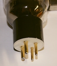
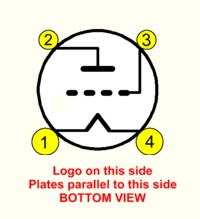
PX25 Data Sheet. Tube for UX4 socket
Description
The PX25 is one of the all time classic audio output triodes. Designed in England in 1932, it was the first tube, designed for larger output power.
|
Guarantee program for first owner.
The first owner can register the tube within 4 weeks after receival, at the Emission Labs website, to participate in the 5 years guarantee program, which is additional to the legal obligations of the seller.
Register here for the 5years guarantee
Features
- Gold Plated Grid (Note8)
- Soft rubber suspended tube base
- Hard metal Construction (Note1)
- Extra large getters
- Hand blown Glass bulb
- Anti-microphonic Anode- and grid suspension
- These tubes are shipped in a high quality dual box
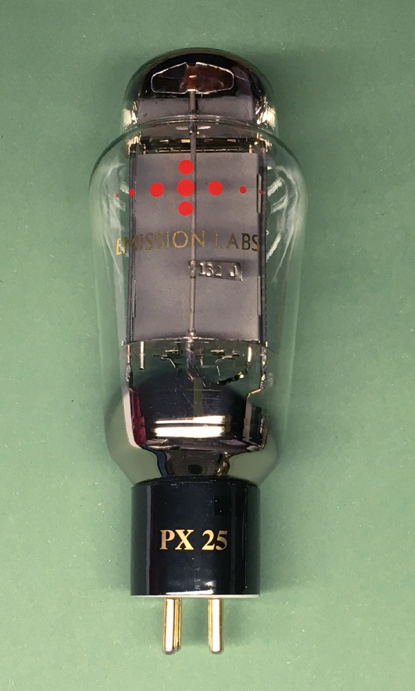
- Tube printing with 24k gold, and red color burned into the glass
- Gold Plated, black ceramic socket.
The Character of the EML PX25
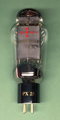
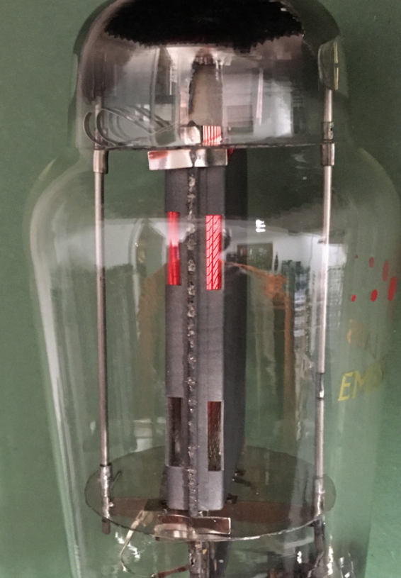
The PX25 is one of the all time classic audio output triodes. Designed in England in 1932, it was the first tube, designed for larger output power. In the old Marconi Numbering System, P stands for 4V heater, and X stands for Power Tube. In Japan, 4Volt heater tubes have always been more preferred for their sound. Moreover, PX25 is a tube with higher gain, it is around 9x unloaded, which is more than twice as much as 300B. This makes driver circuit easier, and PX25 needs less than 30V RMS signal on the grid, for full output signal. The higher gain of PX25 was achieved by Marconi, by increasing the plate distance. We did the same, and the larger side holes, makes also the glow picture nice looking.
Test data of the PX25.
Just a short note, there is PX25 and PX25A. Though only this letter "A" added, these are completely different tubes, and can not replace each other. All data is fully different. PX25A is like a lower power 300B with 4V heater, but PX25 is a higher impedance tube, with wider anode distance. Be careful buying historical tubes, to be used in the same amplifier, it must be PX25 and not PX25A.
Also, Osram specifies the PX25 at 400V, 62.5mA. We do not understand why some vendors of replica PX25 are using 325V as a test voltage, and then write test results which the OSRAM tube has at 400V. This is strange and curious, because such a tube does not replicate original OSRAM data.
Designing with PX25
One of the greatest circuit designers, was D.T.N. Williamson, who based his amazing work initially on the PX25, using 6J5 tubes a driver. Though PX25 was his favorite tube, it was very hard to obtain for him, as it was in production not very long, and already NOS when he started with PX25. Williamson, who worked at MO Valve and Ferranti, noticed PX25 has remarkable similarity with a Triode strapped KT66, and he used this in the late 1940's an alternative to PX25. He published these findings in some issues of WIRELESS WORLD magazine.
This inspiration of Williamson, who used KT66 Triode strapped, as a replacement for PX25, we want to pass this on! There are so many Triode Mode KT66 circuits around, which can be easily modified into PX25 DHT circuits.
Sound of the PX25
We need to understand the design principle of the PX25 tube. This is a tube with much larger plate distance as usual. We just adopted this from the vintage designs. The larger distance will catch your eye immediately, when looking inside the bulb. Not only will this make the glow picture nicer. Also the higher anode distance results in higher gain, and higher plate impedance. Which is what PX25 sound is about. Generally speaking such tubes have a more silkier sound, and a tendency to develop best efficiency at somewhat higher plate voltage. As with all higher gain tubes, there is a higher influence of the tube itself, to the final sound. For the same reason, a good quality transformer is needed, and a good quality PX25 tube is needed, with original specifications. When these factors come together, sound becomes as intended by it's designers, now almost 100 years ago.
As a transformer, we recommend Lundahl or similar quality.
Moreover, many of the greatest sounding DHT tubes were from the 4Volts series. Such tubes are PX25, AD1, RE134, PX4, RS241 or RE604, were always appreciated for their characteristic, more gentle sound.
EML PX25 Filament Ratings |
|
Filament Voltage Important: See notes at page bottom
|
= 4 Volt (AC or DC) |
| Electronic heater modules (See Note) | Only voltage source |
| Tolerance on filament voltage | 4% |
| Filament Current | 2 Ampere |
EML PX25 Maximum ConditionsNot possible simultaneously |
|
| Anode Voltage | 500Volt |
| Anode Current | 90mA |
| Anode Dissipation Continuous | 30Watt |
| Anode Peak Dissipation | 37Watt |
| Highest possible Grid to ground resistor, Single Ended. | 250kOhm |
Highest possible Grid to ground resistor, Push-Pull. |
50kOhm |
EML PX25 Test conditions |
|
| Anode Voltage | 400V |
| Anode Current | 62.5mA |
EML PX25 Test Result |
|
| Grid Voltage, AC Heated | -29V |
| Grid Voltage, DC Heated | -27V |
| Anode Impedance | 1265 Ohms |
| Amplification Factor | 9.1 |
| Transconductance | 7.6 mA/V |
PX25 Operating points, as published by OSRAM | |||||||
Anode vs. Heater |
Anode |
Anode |
Gain |
Rp |
Load |
Power |
THD |
400
|
62.5mA |
25W |
9.5 |
1265 |
3k2 |
6W |
6% |
500 |
50mA |
25W |
5k5 |
8.5W |
7% |
||
Osram data sheets use an auto bias resistor, but are unspecific if anode voltage is vs heater or vs ground. From the dissipation, 400V/62.5mA/25Watt, it should be concluded they meant anode voltage to heater. |
|||||||
SPICE Parameters
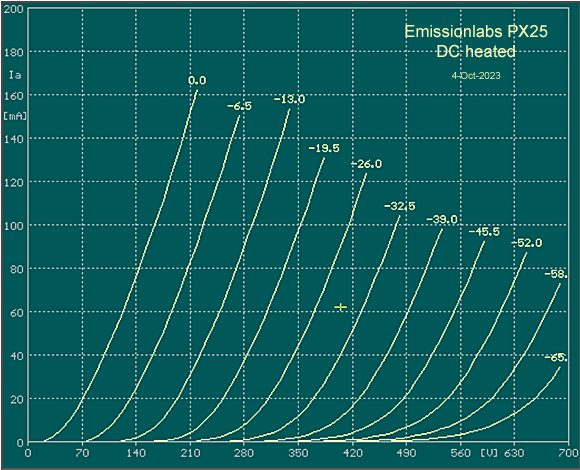
EML PX25 tube curves.
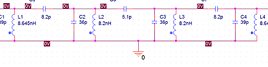
Some recommended Lundahl transformers |
||
Primary Ohms |
Secondary Ohms |
|
| LL1679-70mA | 4k5 |
4-8-16 |
| LL1664-080 | 3k |
8 |
EML PX25 Mechanical Data |
|
|
Size including Socket 148 x 65 mm Pin 1: Heater1 Weight of one tube: Shipment weight for pair in gift box: |
| UX4 Base | |
Notes
- Hard-metal can be used in electron tubes, though this is more difficult to use, and more costly than classic nickel. It results in a more precise Anode distance, and does not damage in shipment. It ensures reproducible tube parameters, and long term stability. Wolfram grids allow the most precise grid wire distance, because wolfram is an extreme hard metal. Best grid geometry ensures uniformity and linearity of the tube curves.
- Gold Plated grids have a few advantages, such as increased bias stability, some protection against accidental overload, and better linearity of tube curves.
- Individual Test data, such as: Matching Data, Grid Current, Vacuum, Filament Current, etc., are on the Certificate that is on the outside of the tube box. Each tube is numbered from the inside, with a metal Tag
- Average Plate Characteristics are made with the Sofia Digital Curve tracer. The curves for the PX25 are plotted, with DC heating. DC heated curves have a shift of the grid voltage of 1/2 the heater voltage vs AC heated. After curve tracing, DC heated curves can be recognized quickly, by the Ug=0V curve not starting at Zero Volt plate voltage. Here, with this tube at appr. +20V plate.
- Heater Voltage. Precise heater voltage is the #1 key to long tube life.
Use of current source modules voids guarantee.
Do not experiment with lower filament voltage, to expect better lifetime. We already specify filament voltage for the best lifetime.
Heater voltage is always defined at the tubes pins itself. There may be some voltage drop along the wires, and tube contacts as well. So voltage measured at the tube socket wiring should ideally be 4.1V.
Original Data Sheets of Osram and Mazda, are mostly referring to DC heating. - Link to wikipedia for Willamson Amplifier