Application Note AN1. Design Considerations for a 5U4G or 274B Tube Power Supply, using a Choke.
Description
In order to achieve good lifetime of a tube, the anode peak current should be considerably less than the maximum emission of the tube.
Design considerations
1) Prevent electrical hum.
Once the mistakes are made,Āit is often impossibleĀto localize them in the power supply, and you'll be looking everywhere at the wrong place, and not find where the hum reallyĀcomes from.ĀThis information applies also when you use silicon diodes.ĀMany sins and mistakes in power supply designĀare made in professional products.ĀWith those, the power supply is often used to save cost. So don't just rebuild a professional circuit without being critical. DIY often pay more attention to the power supply, andĀhave better results.ĀPlease take some time and read this Application before you design your power supply.ĀIt pays off to have a well build and correct designed power supply,Āand the most quiet sound canĀresult onlyĀfrom this.
2) Prevent Mechanical hum
Mains Transformers work relatively close to the saturation limit, because no transformer builder uses a larger core as necessary. This means, that current peaking should be not extremely large. If too large, the current peaks will saturate the core during those peak moments, which will cause a mechanical mains frequency noise in the transformer.
3) Do not use too large first capacitors.
Not only will too large first capacitors cause a lot of hum radiation, but also it will impair the lifetime of the tube, if the peak current comes too close to the maximum emission.
Capacitor input circuits have a larger peak current through the capacitor, as the DC output current of the power supply will be. Yet the maximum emission of the tube filament must be respected. The peak value may not be exceeded, and the DC output current will be lower.
Choke input circuits however, have by nature, a DC current through the choke. Since the choke is directly connected to the tube, each diode of the two will carry a DC current during it's cycle. The current through the tube, has a square wave shape. There is no peak current, and the DC current of the circuit can be chosen higher. Lifetime of the tube will be higher, and radiation wild be lower. The drawback of this circuit is, you need higher AC voltage to achieve the DC voltage (as we do no accumulate voltage peaks here). Another drawback is, you need a larger choke, to compensate for the "missing" first capacitor, and yet get the same smoothening effect.
Overall, a choke input is more expensive because of the larger choke needed, but it rewards with better performance and longer tube life. Also worth mentioning is, a first capacitor suffers a lot, and it the first to fail in older equipment. So a choke input is more professional, but because of higher costs, HiFi manufacturers do not use it.
4) use star ground wiring
 Charge peaks of C1 have always some risk to enter the output, and cause small ripple there. This is because you need to connect C1 to ground, and the C1 ripple current is very high, with a 'spike' waveform. Some small part of that ripple current may find it's way into the amplifier signal, or power supply DC output. Approximately 1 millivolt on the amplifier output becomes audible. Perhaps you once had a situation with a humming amplifiers, and increasing the value cap C1 (as in the above circuit) did not help at all. Though theoretically this should have improved the situation. If this was the case, you should consider the following circuit.
5) Use a Common Mode Rejection circuit
The above is a typical Lundahl Common Mode Circuit. It can be done with two separate chokes, or with two chokes, wound on one core.
There are two good things, this circuit will do. First, if a dual choke on one core is used, most of the spatial hum radiation will be eliminated. That is because the two coils have the opposite orientation to each other. Second, there is no electrical path any more for AC current, from the transformer side to the amplifier side. That is because the left and right side are isolated from each other with coils. Through a coil with high inductance, NO AC current can pass. This means, the capacitive coupling of the mains to the rectifier high voltage winding still exists, but it can cause no AC current any more into the ground of the amplifier.
Some examples of DC Output voltages, Capacitor input:
C1 |
4uF |
Choke |
10 Henry |
C2 |
50uF |
Resistor |
470k 5Watt |
Windings |
60mA |
100mA |
140mA |
| 250 - 0 - 250 | 271V | 239V | 213V |
| 325 - 0 - 325 | 371V | 337V | 308V |
| 375 - 0 - 375 | 440V | 400V | 375V |
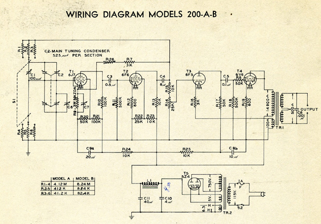
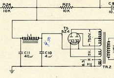 The first product of Hewlett Packard, was the 200A Oscillator, build by Mr. Hewlett and Packard in the world's most famous garage,considered the birth place of silicon valley. Later they modified it to the 200B,to sell 8 units of those to the Disney Studios, their largest business deal they made so far. Look what they used in the power supply: A 5Z4 tube, with a first Capacitor of only 4uF. Though the tube used (5Z4) is specified to have maximum 60uF as a first capacitor, the 'maximum' is not what he used to make a hum free power supply . Full schematic here.
Considerations:
- The actual DC output voltage will depends on factors, like the choke and transformer copper resistance, and (often very high) tolerances on electrolytic capacitors. Some can have -50% or +100% deviation, and that's normal. The data sheet gives only values that are valid for 5000 hours (check data sheets and read it!). What happens after that they do not say, because it is undefined.
- The voltages here are with a DC Copper resistance of 78 Ohm for the choke, and 130 Ohm for the mains transformer. These are average values.
- Use FOIL Capacitors when you can spend the extra money on those. Electrolytic capacitors are the number one factor for failures in older equipment. Reasons are many. The value of electrolytic capacitors can be like -25% and +50% when new. This is nothing strange and can be found in each data sheet. This is when NEW! When they get OLD, things can get a lot worse. OLD means at the end of lifetime. The lifetime of electrolytic capacitors is lower than you may think. Make your guess here. At lower temperatures the lifetime will increases very much, but at high ripple current it will decrease. For low C1 ripple current you need to make C1 as small as you can, not as large as you can. C2 will have no ripple current, since the choke will not allow that. An increase of C1 will not reduce hum of the amplifier, but is bad the rectifier tubes. An increase will even make some amplifiers hum more, because now you have very heavy peak currents flowing though the capacitor. These peaks will radiate into the preamplifier, and cause almost impossible to cure hum. So C1, must be a low value for audio purposes. 4uf is the optimum value.
- larger value of the choke and of C2 will reduce the ripple voltage, and without influence on the output voltage. Roughly, each doubling of the value will reduce the ripple with a factor two.
- If you want to reduce hum with a zero feedback SE amplifier, you must first understand where it comes from. It is normally NOT the HV power supply! With push-pull designs, I think it can never be the HV power supply. I have seen 'zero feedback' PP amplifiers without a power supply choke, and 10% AC ripple voltage on the DC, and no hum at all
Here is a list of things that will help most (in this order):
- Folks, this can not be repeated often enough, but please READ the data sheets. Not just quickly look where the maximum specs are. Read the TEXT part of the data sheet also. Then, be aware, if you touch one maximum specification, you will already not get maximum life time any more, but also you can not touch any of the other maximum specifications any more, unless it says so. So you want to use the maximum voltage? Fine, but then you can not draw the maximum current. Perhaps only 50%. Or, you want maximum current? Fine, but then you can not have maximum voltage them. I know this is boring. But that is no reason to ignore it. This situation is represented by the so called derating curves of (any!) tube rectifier. If this means nothing to you, all I can say is: read the data sheets. We have to say it, data sheets are written by people who know, for people who don't know. And not the other way around.
- Improve your wiring scheme, use 'star' wiring, like in the above circuit diagram. This prevents many wiring mistakes automatically. Heavy AC currents, flowing through too large capacitors will create all kind of hard to understand hum effects. That is because capacitor ripple will find their way to ground in your amplifier chassis, and have common paths with audio signals. 'Ground' is where you have a metal Anode. A ground wire is a wire, and may be no good ground. The only good ground in the form of a wire, is a ground 'star'. A good 'star' grounding scheme, will not require a metal cabinet for your amplifier, and create no hum at all.
- All wires that are in whatever way connected to diodes will radiate a magnetic field. This field can be picked up by amplifier. You can be looking for ever where this (impossible to trace) hum comes from, and it's better to keep the radiated fields low from the beginning. So keep those wires short, keep them away from the pre-amp, and lay them close to the chassis when you can. Important: Allays drill them with wires that have a current in the opposite direction. (For instance transformer AC output windings should be drilled, and also the rectifier heater wires). With adjustable bias voltage, filter this bias voltage very good. It needs to be cleaner than clean.
- Use DC filament heating. AC heating will not sound better, because these will hum, and there is nothing better sounding about that.
- If it helps, put a larger decoupling capacitor over the cathode resistor. With pentodes in the preamp, you may find a lower value will decrease the hum! If so, you have some serious mistakes elsewhere. Try DC heating of this tube, and you may cure it.
- Add more filtering to the HV power supply. The only thing which you can increase as much as you like, is the choke inductance. Or increase C2 marginally. Don't increase C1. Try even to decrease C1. If C1 is s too large this will cause hum also. Too much increase of C2 will cause saturation of the choke core, during start up. This will make the choke stop being a choke at that moment. So what remains is the copper resistance only. This may as well lead to an overload of the poor rectifier tube, and it may take chip off the cathode by repeated arcing, or take the same damage without arcing just as well. Do not think a rectifier tube is a good indicator for too much start up current, just by looking of it arcs or not. Long before arcing occurs, you can already exceeded the maximum peak current, which is the most deadly thing you can do to a rectifier. So in the end, the only safe, professional way is an extremely boring activity called: MEASURE it.