![]()
Some notes about heating tube filaments
Last revised: September 2016
There are several ways to heat a tube filament, each having it's own advantages. Here are a few methods. These are numbered. Explanations are sometime long, so read only what concerns to you!
1) Serialized filaments
The filament current has some tolerance. So sometimes a 5Volt / 1Ampere filament can draw 1.1 Ampere, or sometimes 0.9 Ampere. Only at 5 Volt, the filament temperature is correct. A problem may come if you have an unstabilized DC heater circuit, since the voltage depends on the current load. So at 1.05 Amps the voltage drops slightly below 5V, and at 0.95 Amps it gets a little above 5V.
Even larger problems can come if you serialize a 0.95 Amps tube and a 1.05 Amps tube of the same type! That is because a tube filament is a (very) unlinear resistor. One way or another, this current in the circuit will be the same for each tube. But... what will a heater do, that was produces 5Volts at 1.05 Ampere, and now it is supplied with only 1Ampere? You may expect perhaps one tube has now 4.75V and the other has 5.25V but unfortunately the difference is a lot higher. That is because the a the tube heater has quite a large positive temperature coefficient. (So the opposite of an NTC resistor). This makes the voltage difference much higher as expected. In all cases, when you serialize two volts that are 5 Volts, and put 10V on it, you will definitely not see exactly 5Volts in each tube.
Conclusion: Please use the old basic rule, heaters are to be used in series connection, when they are specified for this. Like P-Series TV tubes. Put 10 random PCC88 tubes in series, and they will all glow with the same temperature. Put them all in parallel, and they will all glow with a difference temperature, which is not what we intended. Well of course nobody will so do. However, with tubes made parallel connection, like E-Series tubes, in the same way, we have to say these should not be serialized. If you parallel 10 ECC88 tubes, they will all glow with the same temperature. Not so when you serialize them! Specially not when they are from different vendors. This is simply wrong use.
If the above is understood, it should be clear it is in general wrong, to supply a current source to a voltage specified heater.
2) Safe operated AC circuits
In one sentence: 5% maximum tolerance, no matter how the 5% adds up. So if you have 5 mains variation already, you should have no additional variation due to amplifier transformers not being fully correct.
3) AC heating
The Control Grid Voltage of a DHT (directly heated tube) when DC heated produces a DC electric field inside the tube Anodes. It is from the 'left to the right' and indeed the tube is not symmetrically loaded by this. There is a misconception that AC Heating will make this effect disappear. The only way to deal with this is use tubes with best possible linearity and then it doesn't matter anyway. The EML tubes of the latest generation have a filament Cathode Tap, to ensure best possible symmetry inside the tube. Connecting this Cathode Tap to the outside world is not possible, since it requires an extra pin. However indeed in all (new generation) EML tubes this Cathode Tap is physically present inside the tube, enforcing in a mechanical way, that the filament electrical center and physical center are the same. (Even Western Electric 300B does not have this feature!). At EML we have drastically reduced AC hum of our tubes this way, and all output tubes can be used AC heated. For driver tubes or pre-amp tubes we do not recommend it.
4) Ultrasonic, or RF heating
Heating a tube Ultrasonic or RF, is a very interesting method, since any noise resulting from this will be eliminated by the output transformer. Besides, it is not audible anyway. The electronics for this is more difficult as one expects, and if anything unexpected will go wrong with the oscillator, the result is a broken filament. So do not experiment with this, unless you are an expert.
5) Safe operated DC linear circuits
This is what most people are using. HOWEVER.... there is no such a thing as a stable regulator IC, specially the low drop types are instable and tend to oscillate at the smallest mistake. Avoid low drop regulators if you are not an expert, and use normal ones. You can have an error with those unexpected and without explanation. Some modules are sold simply instable, and the very moment you make the slightest error, the output voltage can swing wildly, or add a few Volts RF signal to it. What you think is a silly simple regulator IC, is in fact a 10...30 Watt power amplifier with very high gain, very fast, and ultra high feedback. Any small error with the wiring and the feedback will become feed-forward due to inductance of the wire. This requires an RF frequency, for a piece of wire to become an inductor, but these IC's are incredible fast, and it happens before you know it. Then the manufacturer puts tricks inside to make it a low drop type. The normal (not low drop) types these cost only 30 cents in production in China, and for that price you can not expect something good.
Here are some observed problem and things to take care of:
-
People only read a data sheet to find the maximum limits for power electronics. So power Electronics are devices that get warm in some sort of a way. The way to get minimum lifetime, is simply disrespect maximum limits. The more critical you will see such a limit is specified, the more sensitive you should be. This is not just for EML tubes, but for any power device, such as transformers, tubes or silicon. So when a tube datasheet reads: Heater Voltage 5 Volt typical +/-5%, these 5% are maximum limits. At +/- 6% you may get an early defect. So 5V gives better lifetime than 5.2V or 4.8V.
- class="Standard-Text">
'the amplifier sound is good... I check the power tubes later'.
- class="Standard-Text">
Wiring to heater modules longer than 15cm.
- class="Standard-Text">
A Module is not build as separate unit, but integrated somehow in the amplifier, which is dangerous for instability or defects. Here is a better way: The heater electronics must always be build as a separate unit, With one single, thick wired for each function. Like a regulator based on 7805 has only three wires attached to it: Input, Ground, Output. No more. This prevents mistakes of the kind you would oversee much too easy.
- class="Standard-Text">
You are too close to the limit of what devices can do. Data sheets are full of such limits. Close is above 70%.
- class="Standard-Text">
Connecting a volt meter or a scope to the reference input of a regulator, will often cause wildest oscillations. Volt meters do not show this, but read wrong. So you nicely 'adjust' it to 5V and you have another voltage while doing so. Even so voltage can go up suddenly and quickly to effective 9 Volts, and you have a broken heater. So read the next point carefully!
- class="Standard-Text">
Never use an EML tube to test a new build module for the first time. Tubes are too expensive to use them as a fuse. So use a power resistor that pulls 1.5 Ampere from 5 Volts, and after THAT works well, try it with a tube.
- class="Standard-Text">
Use a protection against a broken IC that short circuits output to input. (like a 5.5V BIG Zener diode). You need to read the datasheet of the regulator IC, is it short protected? If there is no information, the answer is: NO. That means if the IC gets defective (and some really do!) they will short the input to the output.
- class="Standard-Text">
Safer is to use 5Volt ICs, and not use low drop types. A risk factor you introduce with IC's that need resistors attached in order to get 5V. Low drop types have higher amplification factor in the internal feedback loop, and are much more sensitive against user mistakes for that reason. Such can blow the tube heater easily when you make a mistake.
- class="Standard-Text">
There must be awareness a tube filament needs current limiting at switch on. The surge current trough the cold filament is up to 8x the normal current if cold. Measure the cold resistance, and use Ohm's law if you are interested in the surge current. DC modules that will force that 8x higher current into a cold tube are tube killers. A good old AC circuit offers natural protection due to transformer saturation at switch on. Yet when you build a module from a MUCH to powerful regulator IC, you introduce a tube damaging factor, by a too high switch on current. When you use a small 2 Ampere current limited IC, this is ideal for tubes like 300B. Protect the IC output with a 5.5V power zener, so you are safe when the IC shorts or oscillates. Use an 8 Ampere low drop IC is very bad for the tubes, as these will supply indeed 6 Ampere start up current to a fully cold 300B tube.
- class="Standard-Text">
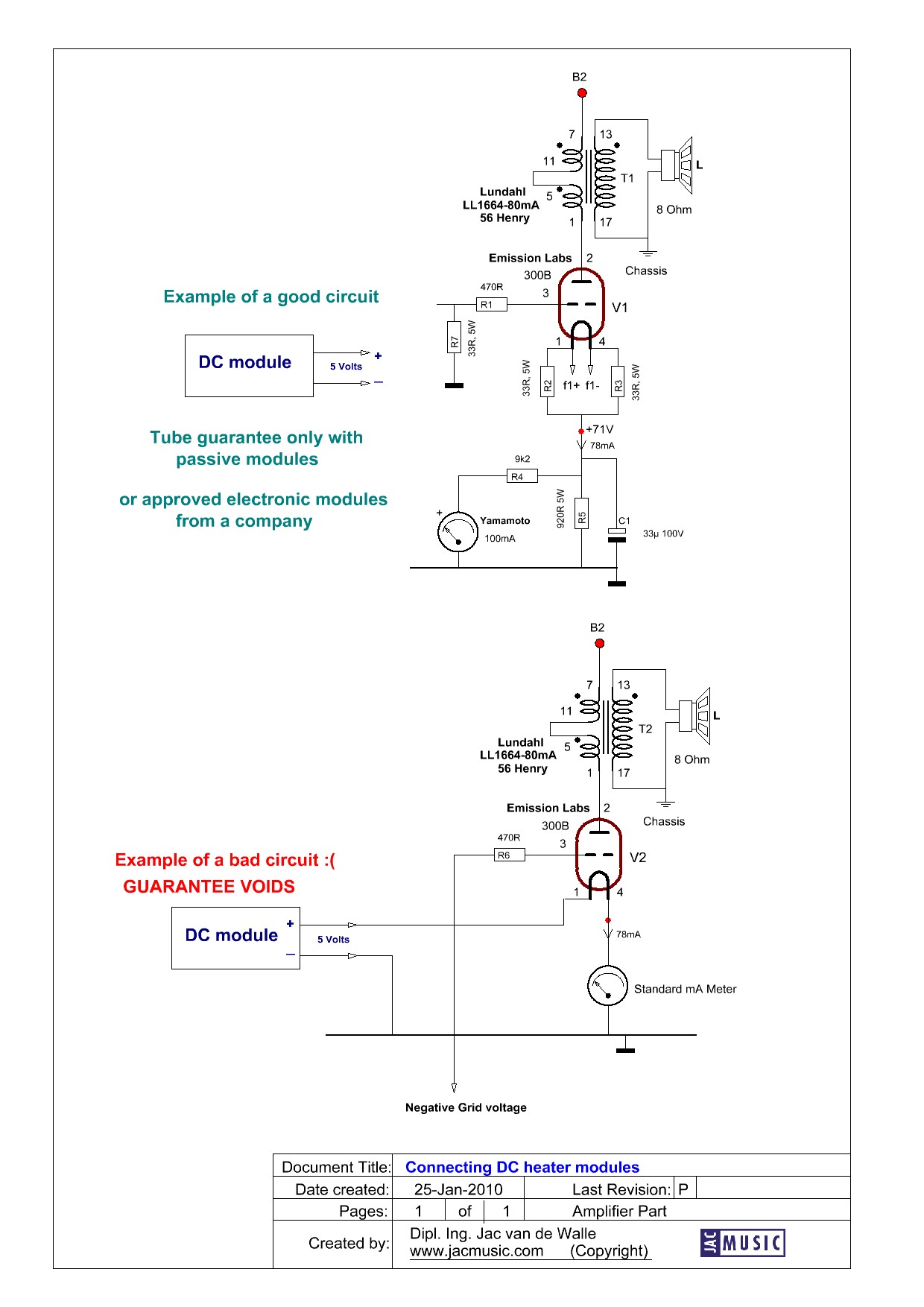
Here is an issue with hum. When connecting the DC module with one end to ground, and the other end to the filament, this greatly increases the sensitivity for the tube for AC ripple. So you might be disappointed with the result. In this case you are amplifying the AC ripple with the tube gain now, instead of rejecting it with the classical (differential working) connection scheme. Either you understand this, and it rings a bell. If you not understand exactly what common mode rejection means, we can not explain it here, but just look at these diagrams and use the right scheme. (The diagram is a part of an kits from www.jacmusic.com)
- class="Standard-Text">
LAST BUT NOT LEAST, THIS ONE. Never use a filament with one end to ground and the other to the the DC module, UNLESS you do not run the tube very hot . This causes the one side of the tube to wear out faster that the other. Here is a drawing that hopefully is self explaining.
Best is always: to set up a normal schematic for AC and then connect DC to that. If that will hum only very little with AC heating, it will sure not hum with passive DC heating, even if residual ripple is on it.
Hint: Try making a DC stabilized circuit with a suited power Zener Diode. You can't go wrong with this.
Subscribe or unsubscribe our Mailing List
©2005. All Rights Reserved.