274A, 274B Data Sheet
Description
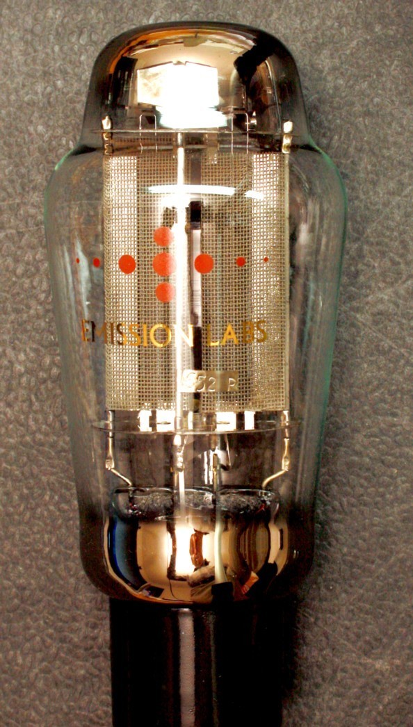
This Data sheet. is about the 274A and 274B, which only difference bewteen those two is the tube base. These tubes are a full wave rectifiers, electrically equivalent to the original Western Electric historical tubes.
|
The EML tubes feature a series connected filament for both diodes togetherm, which has certain advantages. This tube can supply 140mA with a normal C-L-C filter. The 274A and 274B are designed for Audio purposes, and best use is with a small size first capacitor. The EML 274 is also specially suited for applications with relatively high DC voltage. The new ceramic sockets we use sind 2011, are make this possible. |
Guarantee program for first owner
The first owner can register the tube within 4 weeks after receival, at the Emission Labs ® website, to participate in the 5 years guarantee program, which is additional to the legal obligations of the seller.
Register here for the 5years guarantee
Features
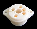
 Soft rubber suspended tube base
- Hard metal Construction (Note1)
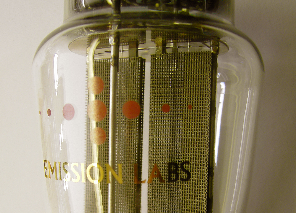
- Extra large getters
- Hand blown Glass bulb
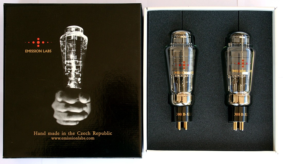
- These tubes are shipped in a high quality dual box
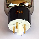
- Tube printing with real gold (metal), red color is glass burned into the glass
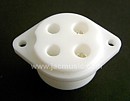
- YAMAMOTO tube sockets highly recommended.
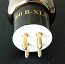
- Gold Plated pins,black ceramic socket.(White bottom.)
Sound Character of the 274A, 274B
It is the most asked question, and behavior of a power supply depends a lot on the type of tube rectifier used, and the way it is used.
With 274A, 274B, the intention is to have only small current peaks through the capacitor, and mains transformer. This will result in less mechanical hum of the transformer, less electrical and magnetical hum radiation into of the preamplifier, an improved sound compared to lower impedance rectifier tubes such as 5U4G, or even solid state rectifiers.
For ultra low ripple, it is recommended to use the Lundahl LL1673 dual coil choke in low CMR configuration. In this configuration, there is virtually no field radiation from the choke. (See link to circuit diagram, at the bottom of this page).
Filament Ratings |
|
| Filament Voltage | |
| Tolerance on filament voltage | |
| Filament Current | |
Maximum ratingsNOT possible simultaneouslyTake one maximum number, you must de rate another READ all notes at the bottom of this Data sheet |
|
| AC input voltage | |
| First capacitor, connected to Anodes | |
| DC output current | |
Typical Conditionsfor C-L-C filter See: Note 2 |
|
| DC output voltage | |
| Total rectified current | |
| First capacitor, connected to Anodes | |
| Choke | |
| Second capacitor | |
For a total (C1 + C2) capacitance above 24uF, a limiting series resistor must be used, so the peak in-rush current through the choke is limited to the saturation current of the choke, or max 600mA, whatever comes first. Otherwise tube damage can result. MUST MEASURE. Can not be calculated in a reliable way. For lowest hum, this resistor is in series with the choke. So you get a C-LR-C filter. In this way 200uF is possible. |
|
274A Mechanical Data |
|
|
Tube Size including Socket:
|
Tube weight |
|
Shipped weight for double box with one pair |
|
274B Mechanical Data |
|
|
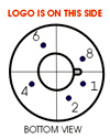
Tube Size including Socket:
147 x 55 mm Connections: Filaments: 8 + 2 Anodes: 4 + 6
|
400 Gram |
|

Some Design Notes for Tube Power Supply
Notes
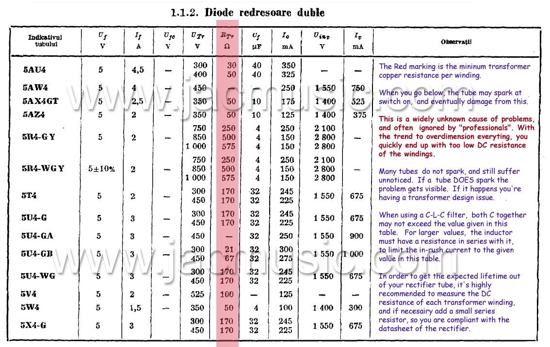
- Good care should be taken when making the design of any DHT rectifier. It must be prevented to have strong current peaks, through the first capacitor, because consequently this flows through the tube anode, and transformer windings as well. The transformer will produce mechanical hum by this, most specially if there is no such thing as windings symmetry by design, or if the windings copper resistance is choosen too low. (Which is a bad tranformer design error). The transformer becomes noisy, and also the tube will suffer. For this reason, the first capacitor (C1) should never be larger than stated in this data sheet. Although it sometimes seems to work 'better', exceeding the capacitor value is a wrong thing to do.
- Mechanical transformer hum, and also tube current peaks are greatly reduced by a smaller capacitor value. In order to achieve the same amount of filtering, simply increase the choke value accordingly. Although it is clear, higher capacitor values come at lower cost than high value chokes, working with a smaller capacitor and larger choke, is always better. The result will be: Lower mechanical transformer hum, less electrical field radiation into the pre-amp, and more lifetime from the rectifier tube. This is why we recommend using largest chokes, and actually today these are not overly expensive. From Lundahl, high value chokes are achievable at the same price as HiFi capacitors, like from a Mundorf or Black gate. So we have to go back to the roots, and use high quality, large value chokes, like in the old days of radio design.
- For best ripple suppression, increase the choke to any value you need, or even use an C-L-C-L-C circuit, as also advised in the historical RCA data sheet. So we are advising this, same as it was advised almost 100 years ago already.
- Higher capacitor values as the data sheet maximum limit may sometimes be used, yet only at very special conditions. This can be the case, if the rectifier is used at siginificant lower voltage and lower current than maximum. Though we advise against it, you may see this occaisionally. This is however often wrong, if not done without carefull measurements, proving peak current is within range. Moreover there is no real need for this. As a rule of thumb, high voltage power supplies are work best with large size chokes, specially at high output current, whereas low voltage power supplies are more conveniently build with larger capacitors.
- Windings symmetry is needed with HV transformers to prevent hum. A HV winding with Cathode Tap, requires most of the time FOUR separated HV windings inside the transformer, which are arranged for the end user as one winding with a Cathode Tap. It is remarkable to see, how transformer manufacturers have forgotten this today. If simply two windings are layed over each other, the inner winding has smaller copper resistance than the outer. With load being not identical this way, a small DC current results, which pre-magnetises the transformer core, and mechenical hum is the result. However we have a tube data sheet here, no transformer construction manual, so we can not explain this in more detail.
- Each tube is numbered from the inside, with a metal Tag.
- Some of our competitors claims to be the only one with a Center Tapped filament, but at EML we build since many years all tubes Cathode Tapped. With rectifiers, the series connection makes the middle of the filaments virtually grounded, when using a heater supply winding with a grounded Cathode Tap.
- Do not experiment with lower filament voltage, to expect better lifetime. If it was that easy, we would make the tubes like this ourselves. The specified filament voltage is the one for best lifetime.