Technical Bulletin 09
Why DC heated tubes can still hum
Written by: Jac van de walle
For who remembers it, some 25 years ago, it was a 'MUST' to heat tubes with AC voltage for 'better' sound. On the forums they would roast you, when you had a different opinion. Any DC heated amplifiers were regarded an unprofessional compromise, for not being able to build a hum free, AC heated amplifier. Slowly this fixed idea has disappeared. Even so, we have to count with it's return, when enough people use DC heating, and some will stand up, to remind about the disadvantages of biasing the tube none symmetric. Around 2010, Yamamoto Soundcraft from Japan silently changed their AC heated A08 amplifier to the DC hated A08-S. Not a word about the humming AC version, and they were not the only one doing so secretly.
Today, we are in the opposite situation, where AC heating is regarded not sophisticated. To make DC heating look something "superb" we see now current driven heater circuits. This is a totally wrong approach. Initially I thought also this was interesting, but I quickly found out there is no technical background about this available. So called technical reports, I have seen them, but I never found one without mistakes.
From the tube manufacturer's view, we can only encourage DC heating, because AC heating has a much larger problem than the hum only The same (terribly large) voltage changes of the mains voltage, comes out at the transformer secondary as well. Now we all know, precise heater voltage is EXTREMELY beneficial for tube life. So we do not say "stay within min-max limits is fine". That is really nonsense. In fact each single percent is very beneficial. Like when somebody says, 0.125V deviation on 5V is not important, this is however 2.5% already. Above 5% tube guarantee voids. Or even with a tube like the 45, which heats at 2.5Volts, 0.125V represents to full tolerance.
So how precise is the mains? Today we are seeing mains voltage changes during 24 hours of 5%, which by itself uses up all tolerance of the tube heater voltage. So there is nothing left for the amplifier itself, and tubes are continuously over heated or under heated. This alone is a major reason not to use AC heating any more.
Add to this, DC heating can be free of hum, when you do it the right way. In this technical bulletin we want to speak about this.
How to achieve DC heating
Building a hum-free tube amplifier without feedback, is difficult, and much attention has to be paid to parasitic or unexpected paths of AC signals.
- DC heating, with unstabilized circuits. This has been done successfully by several manufacturers, but the mains voltage variations are still passed on to the tube heaters. Such circuits can be adjustable, so at least the heater voltage with 220V equipment can adapted for 230V.
- So called filament chokes, have even regulation properties. Did you know that? Yes these do! Provided they are used in a L-C circuit for filtering and not C-L-C. It is widely unknown that an L-C filter provides regulation. It's not a great lot, but they do. Just read the RCA 5U4G datasheet for that. Such a good resource. These people made no mistakes. And hey... there is no patent on it.
- Build your own electronic solutions. Today you can buy voltage regulator ICs with many features build in, such as thermal shutdown, short proof, current limiting, and some protection against IC malfunctioning. All of that for the price of 2$ per 5 pieces. The current limiting works all by itself, when you use a maximum 2Ampere IC to heat a 1Ampere heater, the IC will get into current limiting mode above 2 Ampere (at cold start up). PERFECT!
- Use a switched 5V mains connector power supply. Like you can buy those on Ebay for 3$ and use the internal circuitry. You may or may not have good result with that, but probably the 5V is poorly regulated, mains hum can be present at the output, and the ultra sonic frequency may be radiated.
- When a switched power supply comes in the form of a metal shielded, miniature building block, these can be good quality. It saves the use and wiring of a mains transformer for the 5V.
- Use of specially made power supplies for tube amplifiers. These usually need an AC voltage at the input and supply a DC heater voltage.
- What may not work well, is a hand wired circuit with long wires, using stabilizer ICs. These have a tendency to be instable due to inductive path of the wires, if too long, or too strange set up in the amplifier.
- Below that, and definitely not recommended are low drop regulators from Linear Technology. When the wiring is too long, these can aggressively oscillate in the MHz range. Or even they can be "just" stabile by coincidence, and they seem to work fine. Then, the moment you touch the reference input with a volt meter probe, they oscillate wildly in RF range, and the effective output voltage goes up very much. This becomes dangerous when you use a multi meter, as it would probably indicate even LESS than normal, and effectively heat the tubes with MORE than normal.
Best is always, shortest possible wiring, and use a printed circuit board with only four connections. 2x Input and 2x output.
What causes DC heated tubes to hum?
AC heating IS POSSIBLE though. It really can work, but you really need to understand what causes heater hum, and this is a very difficult subject. You can not approach it by trial and error. Just FYI, when you can read German, here is a 100 years old note from Telefunken, saying they do NOT recommend AC directly heated tubes for a head phone amplifier. With head phones becoming so much more sensitive today, this recommendation is more true than ever. So the assumption is here, to use DC heating.
Provided we have now a DC voltage, the question is: How to connect it to the tube, and what your intentions are. If the intention is to do it simple, use schematic #1, but this is a compromised way. I understand those people who say, it works great. But frankly they never made the compare. Those who really compared both circuits may come to another conclusion.
At a first glance, you can already see schematic#1 is unsymmetric. This discussion we can not briefly add here, but the differences between symmetric or unsymmetric circuits, are discussed at many other places.
The best way is, using a circuit as we are used from AC heating, and at the points where AC Voltage should be connected, simply connect the DC voltage instead. This ensures the circuit stay symmetrical. In the next picture, that would be schematic Nr.2
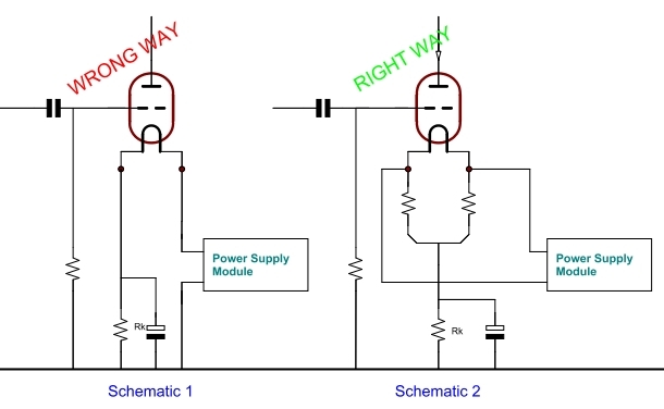
The schematic Nr1. is what we see in use almost everywhere, with or without cathode capacitor, and still this schematic is essentially wrong. All tube manufacturers of DHT say, the cathode of the tube is the center of the heater. Also at EML we say this of course. Yet, as can be seem in schematic Nr1, the cathode is now the left connection. So this gets ignored, the cathode is at the center, and you get stuck in hum problems. In this technical bulletin here, we just use the conclusions directly, but if you are interesting in the technical explanation, read Application Note 06 there is the black box model for a DHT explained, and the real cause for this demonstrated with more technical background.
Let me give you just a brief example here, using a 300B tube.
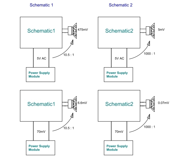
With schematic nr 2 you can have full AC 5V (so 5000mV ) ripple on the power supply module, and output ripple at the speaker terminals is an estimated 5mV, providing a top quality 300B tube, and an amplifier free of any design failures. So this is just a plain AC heating scheme.
This equals attenuation with a factor 1000
With schematic nr 1 the situation is totally another. If we let the power supply module produce 5V AC (so 5000mV). The anode current of the tube responds to heater to Control Grid Voltage DIFFERENCE. So it doesn't matter if the signal is on the grid or on the heater. Without explaining why this is, the equivalent signal on the grid is a half of the signal on the heater. So we can calculate with this, as if 2.5V AC was on the grid. WIth a gain of 3.8 this will give 9.5 Volts AC on the Anode. Using a SE transformer of 3k2 to 8 ohms, means a voltage ratio of 20:1, so from 9.5 Volts AC primary, 475mV will appear on the speaker. So to put it together: From 5 Volts result 475mV.
This equals attenuation with a factor 10.5
 Schematic#1 vs Schematic#2
From the above, we take just those factors, 1000 and 10.5 and apply them for a random power supply module. Let's just say it has 70mV AC ripple, but you must repeat this with the data of your own power supply module.
Hopefully the above makes clear, why the schematic #1 is essentially wrong. In makes the requirements to the power supply module unnecessary high, and there is no reason to use schematic #1. Like when you tolerate only 0.3mV on the speakers, you can have only 3.15mV ripple on the power supply module. This (3.15mV) is quite difficult to measure, you may not even be aware you have this ripple, and think you have a perfect DC voltage, and you end up with a DC heated tube, which is humming.
Applying the same requirement on schematic #2 makes things work much more comfortable. Now we have this factor 1000:1 again. So when we tolerate only 0.3mV on the speakers, this would translate into 33mV on the power supply. Which is still very little, but it can be achieved with normal methods, and measured with a normal multi meter, and the tube will be hum free.
It should be obvious, that for a high gain tube, like EML20B the schematic Nr1 is even more problematic, as the hum signal gets amplified with a factor 20 vs a 300B tube which has a gain of only 3.8.
Particularly when the application is very hum sensitive, so not a loudspeaker driver, but driving a head phone, or use as a pre-amplifier, schematic #1 will become a nasty trouble maker.
I would like to point out here, that manufacturers of power supply modules, talk only about schematic #1. Logically, a hum free modules is the only solution for schematic #1, but there is another problem coming up, even harder to explain, and that is a capacitive path from the mains, via the mains transformer, through the rectifier circuit, into the power supply module, injecting an small AC signal in there, and nobody knows where it is going to. Due to the unsymmetrical configuration of schematic #1, risk of hum pick up from this capacitive signal exists. This is additional reason so use schematic #2.
Using current sources for DC heating?
In few words, guarantee voids if you do so. Some exceptions we can make, and we could offer guarantee on the tubes, with such modules. But these are not many, and the situation has never changed, always when there is a tube issue, users say they used current source modules. Frankly, there were times when these the #1 cause for heater problems. Here is some more information about those.