Saving the world from Solid State
Technical Bulletin: TB-06
PX4 CONFUSION RESOLVED
Finding the right track with PX4.
Written by: Jac van de walle
Abstract
At OSRAM, they made a major data sheet error, which to my opinion resulted from having to use the AVO Valve Tester, which was in England the "State of the Art" Tester, and I find it still a beautiful tester today. It test the tubes at very strange grid voltage, and much too low plate current. Yet with remarkably good result. However you get stuck when you take those test results, and try to specify a tube data sheet like that. I am fully sure, this is what happened. In short: When you look at the tube curves of OSRAM, and extract the tube data from there, you will see this is absolutely NOT in relation with the data table they give. Now, this mistake has been sleeping unseen since 90 years! Until some tube companies (not EML) began to build replicas. I don't know how they manoeuvred along that data, and what they may have noticed, or ignored about it, but it stays the way it is: The OSRAM tube curves and tube data do not match together. So as a tube manufacturer, when you just copy that, you will have the same problem. It should be clear, amplifier designers may take either the tube curves, or the data tables, and definitely amplifiers are now in the field with hidden problems, due to this.
At Emission Labs ®, when building prototypes of the PX4, we ran into this problem, so we had to make some decisions first. That is, we are not going to build those with the original heater current of 1Ampere, because we believe that is not enough to get the strong emission we want. The EML tube has to fulfill also these requirements:
- Significant longer lifetime as the historical tubes or Chinese tubes, as we want to apply the 5 years guarantee program on PX4 as well.
- We wanted the PX4 to be abuse proof, to some limits. Meaning the tube will self-recover from loss of emission by under heating, due to a user's mistake. So in case a PX4 fails, with loss of emission, due to under heating, it will usually self-recover over a period of 5...20 hours, by simply the correct heater voltage again. Unlike historical tubes, which are usually permanently damaged, if you continue with under heating until a failure occurs.
- The tubes can withstand accidental overheating (to some limits of course) much better than historical tubes, and it's direct copies.
So the above was what we began with, and it was quickly done. However, with our prototypes we had a problem. We just couldn't get the specifications right. This was so curious! When the working point was right, Gm was wrong. When we corrected Gm, the working point was wrong. It just didn't seem to make no sense to us, and frankly it delayed the development of the EML PX4 a lot. Later, we found out we were on the wrong track with our conclusions. Believe it or not, but the historical datasheet has some very big mistakes in it. You may wonder how this can be, and if it is true at all, but you are reading here not a copy of some forum bla bla, but the experience of a specialised company, who actually tried to re-build those tubes the original way, called Emission Labs. We say, yes you can always re-build the tubes of course, but when the historical tube curves and the historical data sheet dynamic data are in conflict with each other, we can not copy this, even if we wanted! Needless to say, we choose for the historical curves, and derived the data sheet from that as it is found on the EML website.
This historical error, and how (we think...) it happened is actually quite interesting, and we resolved it, 90 years after the first publication. This is why I wrote this bulletin, just to point this out better.
Now, we sometimes get asked, how come that other companies that build replicas, use indeed the historical tube curves, as well as the historical data sheet values? Well, do not ask us, better ask them, and enjoy the reply :)
The following part is about confusement and mistakes. You can see there, what a mess results when everybody just quickly copies things. We say it again, simply try to derive the dynamic data (Gm, Rp, Gain) from the tube curves, and compare that to the data sheet. Do so with EML, and you will see we did it right. Do so with OSRAM and you will fall off your chair. Do so with some other companies making replicas of PX4, and decide for yourself.
A historical, very confusing situation.
Some 90 years ago, the PX4 tube data sheet was generated, still used today, and there is nothing strictly wrong with it. Yet it is subject to great confusion, leading to Chinese replica tubes being build with wrong data. I am not aware somebody ever noticed, until this technical bulletin was first published in 2015. At EML we tried the same thing as the Chinese, and made the same error. To understand how this happened, we have to go back to the days when this tube was developed in the 1920's by the MO Valve company England, and marketed under the OSRAM and MARCONI brands, beginning in 1928.
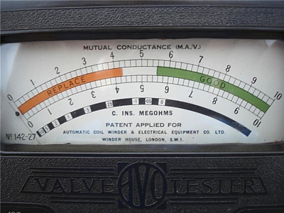 At first there was a low power version, with a 0.6 Ampere heater. Later the high power version with a 1.0 Ampere heater was introduced. This already indicates a lot. So you can see they though 0.6 Amp was a good idea, and later it appeared 1.0 Ampere was a better idea. (And at EML, we say 1.6 Ampere is a better idea). PX4 was developed in England. At that time, the best available commercial tube tester was the English AVO MK1. Today, this tester is almost forgotten, but we have to stand still here, and look at this tester in detail. In those days of the PX4 development, it was ';the'; reference. Later, the Hickok company, had something which they called ';English Test'; on their larger testers, and it was inspired by what the English were doing. So we do need to understand what a ';world standard'; the English AVO Mk1 tester was, and it was only obvious they presented the PX4 data sheet with the settings for the AVO Mk1 in it. This was really a good thing, and they did it that way. I have a good Mk1 in my collection, it works perfect, and accuracy is amazing. However it does test the tubes at very unusual settings. Actually AVO tests the tubes also at very unusual settings, at 0V grid, and 100V Anode. So at OSRAM they just wrote in the data sheet, what test results you can expect, using an AVO mk1.
It seems almost certain, this was the whole reason for this very unusual test setting in the official data sheet, but today we can not ask those old Osram Designers any more, they have all passed away a long time ago.
So we need to work with what they left us. That is the historical data sheet, and the historical tubes which collectors own. The result was: Ra=830 Ohms, and Gm=6mA/V, but you must keep in mind, this was specified at Ua=100V and Ug=0V. So take good note of this simple combination of numbers, as written in this sentence, and from here the mystery tour begins....
How the confusion continued
Unfortunately, the datasheet does not give Ra and Gm at the normal operating points. It's simply left blank. Now you don't absolutely NEED to know, because one can indeed determine the desired operating point by using the tube curves only. However historical PX4 is so rare, I don't think any amplifier designer would use an historical PX4 tube, and the historical datasheet, to design his products, and then tries what the replica tubes are doing in his amplifier. Though it would of course be the best way. To get hold of a really fine, historical PX4 you need to know a collector who leaves you his treasure for experiments. Very unpractical of course. So instead of that, they just take a Chinese tube, bias it at 250V, 48mA and there you are: it works. But does it really...?
We have some lovely misunderstandings on the PX4 replica market today. So you will see the Chinese have made a PX4 with 6mA/V because they copied that number from the Marconi datasheet. But... for the working point for this, they obviously thought 100V Anode and 0V grid is not a good idea. So for the working point they used the datasheet recommendation. So there you see: 250V/48mA and Ra is recommended 830 Ohms, so that was what they copied. Only where is Gm? Just look elsewhere and you see: Gm=6mA/V at 100V anode and 0V grid. So now they had Ra, Gm, and a recommended working point.
The mistake
If you can see the mistake already, well done! But many are unaware Gm is a function of the bias point. And not just a little bit. So the Gm data at 100V anode, is totally another at 250V anode. You see here, what plain copying of other's data sheets can lead to. Even so, the Chinese were not the only one, making this mistake. The weird thing is, the Chinese ';PX4'; with it's funny parameters, was used by many amplifier designers, and nobody ever found out, the parameters were in fact wrong. For this, you have to look carefully at the OSRAM Data sheet, and you will see there, Gm is NOT defined as 6mA/V @ 250V/48mA as the Chinese did it. It is 6mA/V @ 100V/65mA as OSRAM did it. And that is a MAJOR difference, and it would be a big mistake of course to ignore this. Any PX4 like this to my opinion should be called a PX3 or a PX5 but not a PX4.
Let's begin at the beginning
We have to admit it, we made initially the same mistake at EML, but then of course when verifying the prototype point by point, versus the original tube curves of OSRAM, the prototypes appeared unsatisfactory. They they were was not really bad, there is always some tolerance of course, but we just could not make a good bogey tube. We even stopped the PX4 project initially.
I am sure you already found this text confusing, and it is indeed. So let's begin at the beginning, and make an inventory in table form of what we know, and what we do not know about the PX4. That will result in the following table, where the red boxes are simply never filled in by OSRAM. I repeat, the background for this, to my opinion for 99% sure, was the AVO MK1 tester.
So here is the inventory of known data. These is all that was published by Osram: (here the original data sheet)
Original Osram Specifications | ||||
| Anode Voltage | 300V
(Max) |
250V |
200V |
100V |
| Control Grid Voltage | -42V |
-32V |
-28V |
0V |
| Anode Current | 50mA |
48mA |
25mA |
65mA |
| Anode Dissipation | 15Watt |
12Watt |
5Watt |
6.5Watt |
| Bias Resistor (AC heated) | 900 |
740Ohms |
1200 Ohms |
|
| Load Resistor (Ra) | 4000 Ohms |
2400 Ohms |
4500 Ohms |
|
| Gain (Mu) | Left Blank by Osram
|
Left Blank by Osram
|
Left Blank by Osram
|
5 |
| Transconductance (Gm) | Left Blank by Osram |
Left Blank by Osram |
Left Blank by Osram |
6 mA/V |
| Anode Impedance (Rp) | Left Blank by Osram
|
Left Blank by Osram
|
Left Blank by Osram
|
830 Ohms |
| Estimated power Output | Left Blank by Osram |
Left Blank by Osram |
3.5 Watt |
|
So here is a problem for those tube Manufacturers that want to re build the PX4. Some of the data is missing as you can see. Moreover in the original datasheet, it is indeed marked that Gm , Rp and Mu are defined at 100V anode and 0V grid, but this is written there very confusing. So some day, somebody may decide a PX4 has Rp = 830 Ohms and Gm = 6mA/V. Then this needs an operating point, and there is one for 15 Watt and one for 12.5 Watt. Then combine this 15 Watt operating point, and the result is like in the next table. Now of course you are free to do so, but such a tube differs from to the OSRAM PX4, and that to my opinion that is too far away from a PX4 to call it a PX4. I will explain this more detail, why I think so.
The Chinese result is published like this on their website.
|
||||||||||||||||||||||||||||||||||||||||||||||||
On a Chinese tube manufacturer website, there is a graph they made with the Sofia tester, and they write this is made with AC heater. I do not think so, because I have the schematics of the Sofia, and I own two of them, and they have DC heating, and no option for AC heating at all. They don't have the option in hardware, and not even a correction in software. So, ANOTHER mistake. This doesn't matter a great lot for a tube with -50V Control Grid Voltage, but you are indeed measuring the tube at 2 Volts offset. (Half the heater voltage). Just want to bring this up here, and do the math precisely. Some numbers on that graph were hard to read, so I photo shopped the revised Control Grid Voltage in the graph, including 2 Volts compensation for the DC heating. And now we are getting something, and the result looks like this:
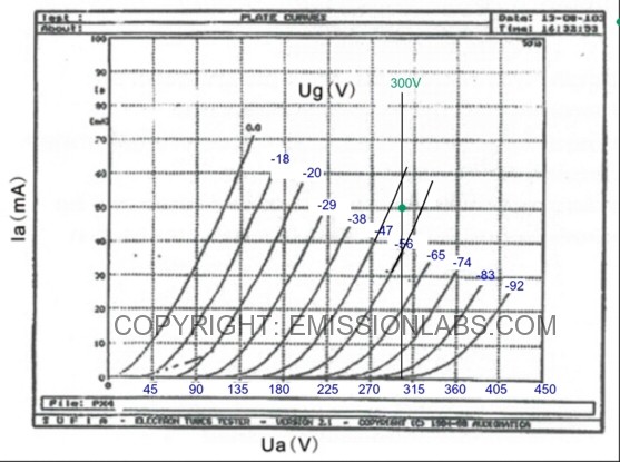
Chinese PX4 on Sofia tube tester, bias point marked by myself.
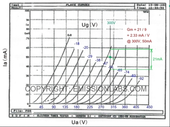
Chinese PX4. Reconstruction of Gm Data
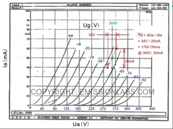
Chinese PX4. Reconstruction of Rp Data
The gain (Mu) can be calculated, it equals: Mu = Rp multiplied by Gm
Chinese PX4 Specifications reconstructed from the above tube curves: | |
| Anode Voltage | 300V (Max) |
| Control Grid Voltage | -51V |
| Anode Current | 50mA |
| Anode Dissipation | 15Watt |
| Bias Resistor (AC heated) | 900 |
| Load Resistor (Ra) | 4000 Ohms |
| Gain (Mu) | 3.9 |
| Transconductance (Gm) | 2.33 mA/V |
| Anode Impedance (Rp) | 1700 Ohms |
| Estimated power Output | 4.5 Watt |
To prove the above graphical construction is the right method, I will do so with the OSRAM data sheet, and reconstruct the values for Gm, Rp and Mu, at 100V Anode and 0V Grid. The result should be: Rp = 830 Ohms and Gm = 6mA/V
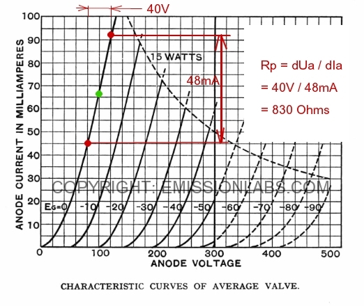
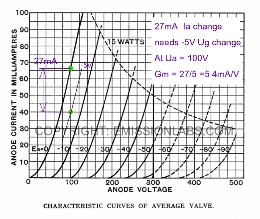
As you can see, I do not fully find 6mA/V but only 5.4 but it has to be said this method of only going down vertically (and not going up as well) in the chart, it gives some small error. However constructing is not possible otherwise in this way, as there is no data in this chart for positive Control Grid Voltage. (Any curves for positive Control Grid Voltage may not be just be penciled in, as dynamic tube data changes suddenly some 10% above +0Volt. You can check that yourself with curves of some triodes that do present positive Control Grid Voltage curves indeed) So, finding 5.4 instead of 6 proves just the graphical construction method is correct, and we know the missing 10% is from not having the positive Control Grid Voltage data available. We don't follow up on this here, as there is no need.
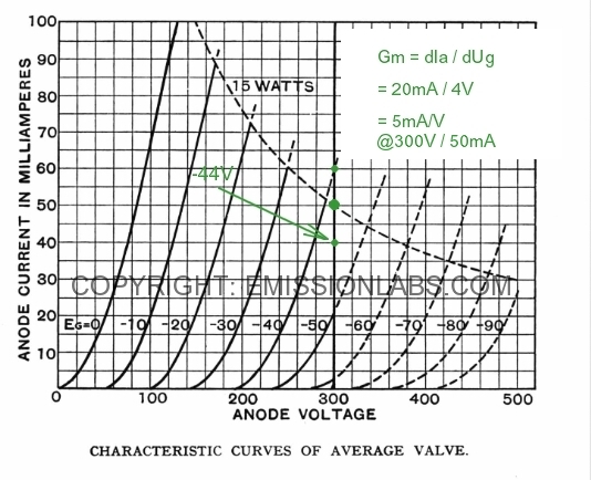
What are going to do: It is possible to construct the data from the normal operating points though, so at 300V and 250V. This will be done in the next charts, and this is going to lead to very precise Gm data, as needed.
Finally completing the OSRAM data sheet after 90 years :) .
We can just re construct the missing data, by using the tube curves.
Original Osram Specifications in black
| ||||
| Anode Voltage | 300V (Max) |
250V |
200V |
100V |
| Control Grid Voltage | -42V |
-32V |
-28V |
0V |
| Anode Current | 50mA |
48mA |
25mA |
65mA |
| Anode Dissipation | 15Watt |
12Watt |
5Watt |
6.5Watt |
| Bias Resistor (AC heated) | 900Ohms |
740Ohms |
1200 Ohms |
|
| Load Resistor (Ra) | 4000 Ohms |
2400 Ohms |
4500 Ohms |
|
| Gain (Mu) | 4.9
|
5.6 |
4.6 |
5 |
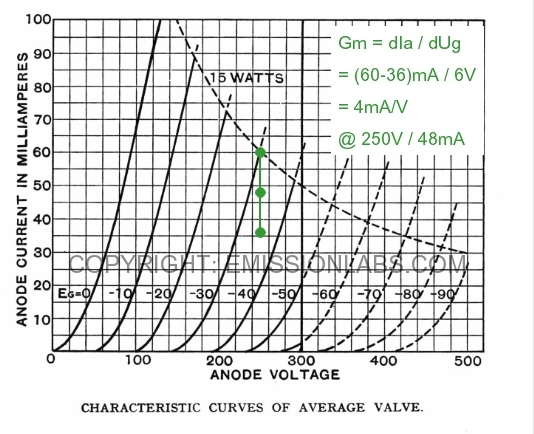
| Transconductance (Gm) | 4mA/V |
5mA/V |
3.2mA/V |
6 mA/V |
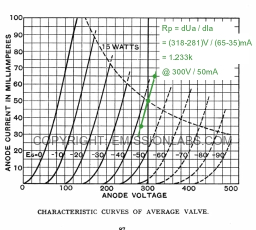
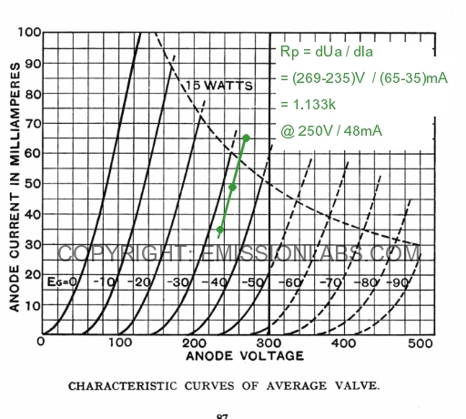
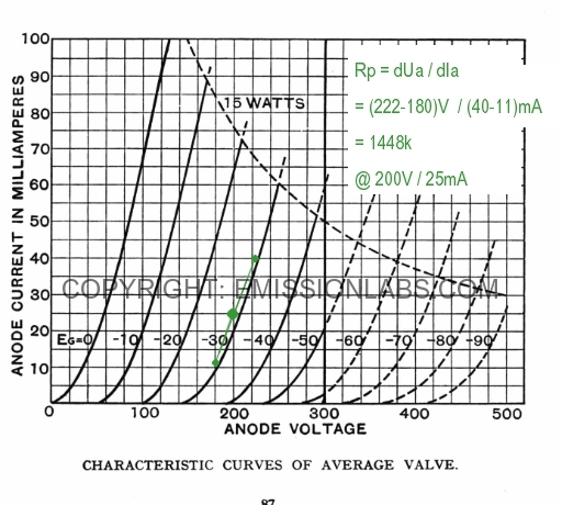
| Anode Impedance (Rp) | 1233 Ohms |
1133 Ohms |
1448 Ohms |
830 Ohms |
| Estimated power Output | 3.5 Watt |
|||