SOME DESIGN NOTES FOR POWER SUPPLIES

Read this information carefully!    Many mistakes are made with the power supply, causing the amplifier to hum.  Once the mistakes are made,  it is often impossible  to localize them in the power supply, and you'll be looking everywhere at the wrong place, and not find where the hum really  comes from.  This information applies also when you use silicon diodes.   Don't think you know it all.  Many sins and mistakes in power supply design  are made in professional products.  So don't just rebuild'something'.  DIY often pay more attention to the power supply, and  have better results.   Still take some  time and read ALL OF  THIS before you design your power supply.   It pays off to have a well build and correct designed power supply,  and the most quiet sound can  result only  from this.    
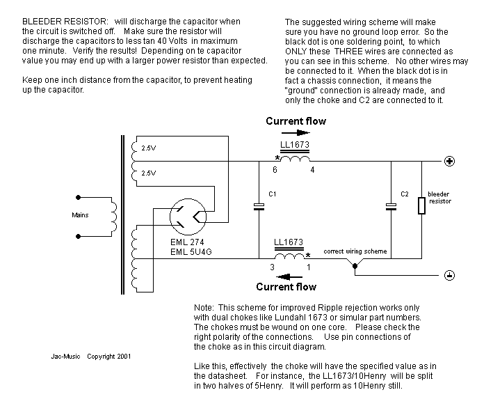
Scheme for high quality audio chokes, with dual coils

C1
4uF
Choke
10 Henry
C2 
50uF
Resistor
470k  5Watt
 

Some examples of DC Output voltages:

Windings 
60mA
100mA
140mA
250 - 0 - 250
271V
239V
213V
325 - 0 - 325
371V
337V
308V
375 - 0 - 375
440V
400V
375V

Notes:

  1. class="Standard-Text">The actual DC output voltage will depends on factors, like the choke and transformer copper resistance, and (often very high) tolerances on electrolytic capacitors. Some can have -50% or +100% deviation, and that's normal. The datasheet gives only values that are valid for 5000 hours (check datasheets and read it!). What happens after that they do not say.
  2. class="Standard-Text"> The voltages here are with a DC Copper resistance of 78 Ohm for the choke, and 130 Ohm for the mains transformer. These are avarage values.
  3. class="Standard-Text">Use FOIL Capacitors when you can spend the extra money on those. Electrolytic capacitors are the number one factor for failures in older equipment. Reasons are many. The value of electrolytic capacitors can be like -25% and +50% when new. This is nothing strange and can be found in each datasheet. This is when NEW! When they get OLD, things can get a lot worse. OLD means at the end of lifetime. The lifetime of electrolytic capacitors is lower than you may think. For instance an 85°C type, actually used at 85°C it is only 6000 hours. (Data: Vishay capacitors). At lower temperatures the lifetime will increases very much, but at high ripple current it will decrease. For low C1 ripple current you need to make C1 as small as you can, not as large as you can. C2 will have no ripple current, since the choke will not allow that. An increase of C1 will not reduce hum of the amplifier, but is bad the rectifier tubes. An increase will even make some amplifiers hum more, because now you have very heavy peak currents flowing though the capacitor. These peaks will radiate into the preamplifier, and cause almost impossible to cure hum. So C1, must be a low value for audio purposes. 4uf is the optimum value.
  4. class="Standard-Text">A larger value of the choke and of C2 will reduce the ripple voltage, and without influence on the output voltage. Roughly, each doubling of the value will reduce the ripple with a factor two.
  5. class="Standard-Text">If you want to reduce hum with a zero feedback SE amplifier, you must first understand where it comes from. It is normally NOT the HV power supply! With push-pull designs, I think it can never be the HV power supply. I have seen 'zero feedback' PP amplifiers without a power supply choke, and 10% AC ripple voltage on the DC, and no hum at all

Here is a list of things that will help most (in this order):

    1. class="Standard-Text"> Improve your wiring scheme, use 'star' wiring, like in the above circuit diagram.  Heavy AC currents, flowing through too large capacitors will create all kind of hard to understand hum effects. That is because capacitor ripple will find their way to ground in your amplifier chassis, and have common paths with audio signals.  'Ground' is where you have a metal Anode.  A ground wire is a wire,  and may be no good ground.    The only good ground in the form of a wire, is a ground 'star'. A good 'star' grounding scheme, will not require a metal cabinet  for your amplifier, and create no hum at all.
    2. class="Standard-Text">All wires that are in whatever way connected to diodes will radiate a magnetic field. This field can be picked up by amplifier. You can be looking for ever where this (impossible to trace) hum comes from, and it's better to keep the radiated fields low from the beginning. So keep those wires short, keep them away from the pre-amp, and lay them close to the chassis when you can. Important: Allays drill them with wires that have a current in the opposite direction. (For instance transformer AC output windings should be drilled, and also the rectifier heater wires).
    3. class="Standard-Text">With adjustable bias voltage, filter this bias voltage very good.  It needs to be cleaner than clean.
    4. class="Standard-Text"> Use DC filament heating. AC heating will not sound better, because these will hum, and there is nothing better sounding about that.
    5. class="Standard-Text"> If it helps, put a larger decoupling capacitor over the cathode resistor. With penthodes in the preamp, you may find a lower value will decrease the hum! If so, you have some serious mistakes elsewhere. Try DC heating of this tube, and you may cure it.
    6. class="Standard-Text"> Add more filtering to the HV power supply.   Take a larger choke, or increase C2.  Don't increase C1.  Try even to decrease C1.  If C1 is s too large this will cause hum also. 

Subscribe or unsubscribe our Mailing List
© Emission Labs ®. All Rights Reserved.