Description In short: To use the V4 (Center tapped tubes), the fastest way is: Connect a floating power supply to the heater connections, called H1 and H2 in the datasheet. The voltage of this power supply is the rated voltage of the tube. So 5V for a 5V tube. Take care NOT to connect the heater voltage to the center tap, because that would burn out one half of the heater, of course. Then when connected to H1 and H2, the heater will already glow normally. Now, the question is, where is the cathode? As a cathode, use the center tap! So connect the auto bias resistor, to the center tap. Do it simply like this, and already the tube will play, with less parts, and better technical result. AC or DC heating: There has always been discussion about what is the best way to heat a Directly Heated Tube (DHT). Must it be heated with AC or with DC? Must it be heated with an ultra sonic signal perhaps, like 25kHz? This all deals with the same generic requirement: Lowest hum, at lowest technical effort. This is what the V4 tubes are made for! The ideal tube. As we all know, with a DHT, the Heater and the Cathode are combined. Actually we call it the "filament". Reason for this is, this geometry gives the best tube curves. The ideal tube geometry would be a (flat) construction, and not something circular as with indirectly heated tubes. So this is why DHT are made. This flat construction would be for the anode, for the grid, and for the cathode. For the anode and grid, that is easy to do, but not for the cathode. Just suppose, we would have a planar cathode indeed, and we would make it glow hot read. This would give problems, that can not be solved. Such as: Too much heat, too much emission, too much power consumption, etc. A practical solution would be, an array of thin wires, basically doing the same thing. So those wires, act the same way as an emissive surface. There is one disadvantage though: There is no cathode connection any more. Instead there are two connections, and heater and cathode become the same. This gives the infamous hum problems with AC Heating. With DC heating the hum is gone, but other problems such as use the grid field is not homogenous any more. The left side and the right side have not the same dissipation, and not the same working point. For instance you have a 300B with +5V DC heating. This +5V distorts the grid field, and it distorts the anode field. At Emission Labs ®, we had the idea to add a center tap to the tubes. The advantage of this will be described in this application note. The center tap is now used as a real cathode. This doesn't solve the above mentioned field distortion, but it does solve some other problems. The practical tube. In most tube schematics we see two centering resistors at the cathode. The point were these two connect, becomes an artificial cathode. Even so when the two resistors are identical, there is still a small offset, caused by the tube geometry per definition. (There is no solution for that, and this gets a larger effect when the heater voltage is higher). A potentiometer can be added, to center the artificial heater, adapted to the individual tube. Note, at some point BEFORE the end of lifetime, older tubes probably need re-adjustment more often. Does a well adjusted artificial center tap solve the problem? No, not completely! WIth a non center tapped tube, the cathode current will not exit the tube directly at one connection, but must follow the path through the balancing resistors. This is definitely not a nice way, and besides AC signal will be absorbed in those resistors, if they are not capacitor bypassed. Resistor values can be in the range of 2x 30 Ohms with a 300B, whereas the tubes internal impedance is 700 Ohms. This ratio is not neglectable, and a small a fraction of the output power may get lost. Of course one can also take much lower resistors, but then these resistors consume a lot of heater power, which makes the heater supply more costly. So one way or another the balancing resistors waste energy. We have not even talked about what is does, to pass the sound signal though these resistors, and or bypass capacitors. So this whole construction is indeed a compromise, and yet we see it in almost every amplifier. Is there a solution? Yes there is. It is called the center tapped tubes by Emission Labs ®.
The Center Tapped tubes (V4-Version) have a center tapped heater inside the tube bulb. So the heater itself is split into a right half and a left half, and in the middle we connect a center tap. This center tap is a fifth connection for the triode, and electrically speaking it becomes a REAL hard wired cathode. So the center tapped tubes have this one connection that we call the cathode, and two other connections that we call the heater. Such a triode has five connections, just like an indirectly heated cathode, such as 12AT7. DHT Tubes with a real (Physical) center tap of the filament. We have been producing the center tapped tubes for quite a while now. So the filament of those have a real physical center tap. It is a real metal connection in the tube base. Only we never had the idea to connect it to the outside world. Reason for having the center tap still, at production the tube is forced to be mechanically as symmetrical as we can do. The result is a drastically reduction in tube hum, ever since we build those. The idea is now, to connect this center tap to the outside world. This means we need five connection instead of four, and the UX4 base can not be used any more. We need to use an octal base for such tubes. This center tap opens a world of possibilities.
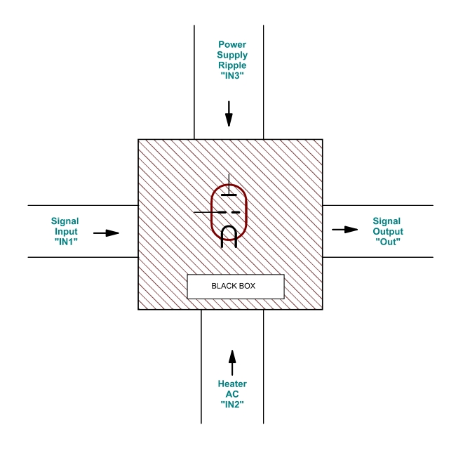
From the above left schematic 1, it can be seen there a common path for the Music signal, and the heater current. Needless to say this is source of problems. The middle schematic has so much simplicity, it may seem familiar to you. Though this is a new method. The advantages are: 1) Anode Current is easy to measure (This is impossible with the left schematic) BLACK BOX APPROACH It is widely unknown, that Directly Heated Tubes (DHT) have a very high rejection ratio of the AC heater signal. For this reason, the left schematic (above) is a bad one to use. Let's just look at a tube as a black box, which is an amplifier in our case. So, something goes in, something goes out, and we have gain. There are two power supplies connected, with some amount of AC hum on it. This hum we want rejected.
We consider the rejection ratio for the schematic 1, but to make it simple we just use a numerical example. Suppose the input, IN1 = 1V~, and the tube gain is 4. Then we have 4V~ on the output, called "Out". So far, so good, and we all know that. There are three signals, applied to the tube, but power supply ripple we are not looking at here. So we consider only the AC heater "Signal" and the Tone input signal. Of course we expect nothing of the AC heater signal to appear at the output. However, since our black box is not ideal, something will appear at the output still. Consideration of above schematic 1 There is no rejection of the heater AC residue. In fact it is even amplified by the tube, when it's gain is higher than 2x. So the output signal will be: Out = IN1 * Gain + IN2 * Gain/2. In a practical situation, a 300B amplifier can be considered low hum, when you have less than 1mV AC on the 8 Ohms speaker output, whereas not so good amplifiers present 5mV hum or more. We calculate here with the 1mV. This translates into appr 20mV on the tube anode. We are going to assume now, all of that is injected via the heater. How much would it need on the heater, to get 1mV on the speaker (meaning 20mV on the Anode). 20mV on the anode, with a gain of four, means 5mV on the grid. Or, we can have 10mV on the heater, which has the same effect. So, 10mV AC on the heater gives 4 x 5mV AC on the anode, so 20mV . This is a GAIN of factor 2 (or 3dB)
Consideration of above schematic 2 This one works much better. It can be compared with a classical AC heated schematic, and without a center tapped potentiometer, you can come down to say 8mV on the speaker output. This is for full 5V AC signal, on the heater, or input "IN2". This 8mV on the speaker would mean 32mV on the Anode. This is a REJECTION with factor 156 (or 22dB). We can reduce the 8mV on the speaker to 1mV, which would reduce the 5V AC voltage to 625mV
How to design? Whatever you do, schematic #1 is non-prefered since it has no ripple rejection ratio, but even 3dB GAIN. Such a schematic will only work with extremely quiet DC power supply, of the kind that many will find difficult to build. It is better is use schematic #2, since it's ripple rejection ratio is so high, you can do without electronic regulation. Simply a passive stabilized circuit will do the job. Like a plain C-R-C circuit is FINE already, and will outperform circuit #1 using an integrated circuit. So the difference between schematic 1 and 2 is 25dB less heater hum. Where does the center tap come in? You may object, schematic #2 can be achieved also with two centering resistors. This is true, but not quite. If you want really good centering, you will need very low values of those resistors, and they use considerably energy. This makes the power supply capacitors larger, the transformer also, and you have larger charge peaks for the capacitors, which will radiate into other parts of the amplifier. So the resistors are chosen often at a much higher value, to make things more practical. Then, in the end they become a bad compromise, and you loose the good rejection ratio you had in mind. Note, when they get too high, you also start to dump output signal in those resistors, as the anode signal must pass through them. So the amplifier gets less efficient. In a practical situation we talk about 0.3 Watt loss in a 300B Single Ended stage. Also the artificial center is connected via a resistive path, and all of this is not a clean and nice way. The center tapped tubes do a much better job here. They are not a compromise, they give a real true center tap, directly on the cathode itself, and yet it consumes no heater power. The advantage with high gain tubes As the heater ripple gets amplified by half the gain of the tube, the V4 version becomes very useful with tubes, such as the 20A, 20B, or 30A. The advantage with high power tubes Since you loose appr 3% of the tube output power in those centering resistors, it is simply nice to have 3% more output power from a center tapped tube. The advantage with low power tubes Such a tube is often used with very high efficiency speakers, and anyone who has experience with such speaker systems will know that residual hum is a major issue. It is obvious that 2mV hum from the amplifier. is very unpleasant with 106dB speakers, but you won't hear it with 90dB speakers. So with horn systems, when using the V4 tubes, you are likely to get lower hum, since you are better protected from some of the very nasty, and unexpected mechanisms that cause your amplifier to hum via the power supply. Can you use them as normal tubes? Yes you can! If you don't want to use the center tap, just leave it disconnected and you have a regular four-connection DHT triode again. You are encouraged to discuss it on the EML forum! For amplifier designers, the below links may be helpful.
Subscribe or unsubscribe our Mailing List © Emission Labs ®. All Rights Reserved. |

